Small Library idea

OK, here is, I think, the framing largely done. How things get attached to each other has not been determined. Also the roof beam and loft beams things have not been run by an engineer. According to my calculations, I should be at least close.

I added OSB sheathing. I don’t know what sheathing will be used. All choices are about the same thickness.

I am thinking of working on fixed lighting, HVAC and wiring next. Any advice?

Also, can anyone find the gremlin that is adding to much weight to my model?

Thank you all for following along.

Best,

Cook

Library v3.skp (4.0 MB)

Here’s a little something.

This beam could go up:

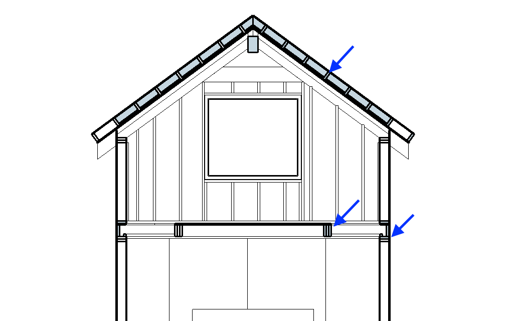
Or, you could notch the Rafters:

The second way tightens up that big gap and supports the roofing material all the way to the peak. The first example above leaves a wide ridge cap.

If you notch the rafters, you can click into the front rafter, draw a perpendicular line just before the 45, and cut it off straight with Push-Pull. Then Push-Pull until your rafters overlap above the peak. Trace the notch by drawing a line downward on red to the center of the top of the Rafter Beam, over to the edge of the Rafter Beam and then down again. Push-Pull to cut the notch out.

This furring is off by a hair (did you adjust your 16th button again?).

Click on long edge only, use Move Tool to drag the long edge to the corner of another long edge (directly over lower right angle corner).

Bring squared board edge to peak with Move Tool.

Square Hair

Delete all but the 2 peak boards.

Select one of these. Use Move Tool, selecting at the edge nearest the peak. Click, ctrl (to Copy), Move to lower edge of copied board. Click. Enter x34 and Press Enter.

Now you will have an incorrect number of boards on you roof:

But that’s okay because you didn’t click any other buttons, so you just go ahead and type in x35:

Now you’re the Puppet Master and Components are mere pawns in your Copying games. Or, you could think of it as being able to enter different numbers of copies until you find a number that works instead of Selecting, Copying and Moving from scratch each time.

I recently fought a battle involving sheetrock, ladders, scaffolding, and a big faux beam. The sheetrock won. But here you need to cut a notch in the sheathing.

Click-in, use Pencil to trace along beam, Push-Pull cut out section. Move out to inspect handy work:

Now you’re faced with a crucial question: remove material because it cannot been seen (the unseen material theory of file size reduction), use the dropper to put material on the edge that has none (The put materials everywhere because otherwise it feels incomplete because everything else has materials theory), or just leave everything alone and move on (The leave it alone theory)?

Regardless, fill in the little triangles above the beam.

45 the tops of your Gable Studs off.

1 Like

3D,

Thank you again for your detailed response. You dealt with the part of the framing that I am waiting on my contractor buddy to chime in on. But I did miss the 1/16" thing again. Aargh.

Any chance you have some input into wiring and lighting? Not specifics of where to put lights or receptacles, but how to model them. My usual wiring diagrams look like this:

Which I don’t think will be helpful here.

Cheers,

Tom

So I cut the gable sheathing around the roof beam. To do so, I

  1. Went into the gable sheathing context, selected the gable peak sheathing bit and cut it
  2. Went into the beam context, “Pasted in Place” the peak sheathing.
  3. Used solid tools to trim the sheathing.
  4. Selected and cut the gable peak sheathing.
  5. Went back into the gable sheathing context and pasted in place the newly trimmed peak bit.

As regards to the peak of the roof, I am not sure what to do there or with the roof because I am not sure what kind of venting I might want there. It turns out there are a lot of options for creating a well vented and well insulated vaulted roofs.

Regards,

C. Cookie

I’ve been thinking a little more about the SU DO Extension (pronounced “pseudo”, or simply “Su Do”). Think of the thing to DO, press the SU DO button and sha-zang, done. It could work marvels with your sticky 1/16 button. SUDO: remove the 1/16 stuff I don’t want. It’s an extension that is just crying out to be developed. Other than that, you may have to disable the 1/16 switch directly on your mother board.

Maybe something like a reflected ceiling plan would work for you.

This person (Tammy Cody) does something that might give you some ideas:

Lighting & Electrical Plans in LayOut – SketchUp for Interior Designers

Not a lot of images there… You can see an image here:

Join the Membership - SketchUp for Interior Designers

THIS ONE>>>Or here: How to create lighting and electrical plans in SketchUp and Layout — The Little Design Corner

You could buy the electrical symbols: Store - MasterSketchUp.com

Do you want to do wiring and lighting in the model, or in a plan?

FYI - looks like you left your logic gate open.

Ah - Solid Tools could be a good way too.

Forgot about insulation… Sheath roof, hang backing, make an insulation void:

Something like this?

I like that a lot. I am still struggling with sheetrock vs wood lath for the loft ceiling. Sheetrock will be cheaper, but wood will look a lot better for a library.

Thank you for the links. They will be most helpful.

I am planning on putting the electrical in some form in the model or models. Wire routing, the whole bit. That will help, I hope, avoid pitfalls and pratfalls during construction.

Luckily there will be no plumbing.

Cheers,

T. Chip

NOTE TO READERS: BORING DETAILS ABOUT ELECTRONICS BELOW

There is no logic gate open. The second switch controls the second brush on the motor, thus controls speed. Everything was controlled from a small hidden box (with a simple, but custom PCB) wired to two custom switches on the dash. Each switch had an LED center indicating if the system was on and the speed setting. I know, one 3PDT switch would have been cleaner, but the customer wanted confusing bling. It worked, which is all my customer cared about. Probably the most expensive wiper system ever installed on a VW Thing.

It became even more expensive when he installed a 12V battery (which he was told not to do).

Either way could look nice. I just placed a 2x4 in there to give 3.5 inches for insulation. Something I would focus on is how much of the rafter is still visible (and proportion to fully visible rafters/beams). At some point you may just want faux beams. And hey, if you decide to add skylights for ventilation, the sheetrock will look worse faster as water leaks in… so there’s that.

Maybe you go with a 1/2 rectangle and basically Push-Pull wire ‘boxes’. Or you could go with ‘lines’ and Follow-Me. Depends on the detail… I’m guessing you want the fun of the details.

It’s really going to start to smell in there.

That’s nothing. Here’s the method I’ve developed for boring people.

Summary

Coffe Routine


  • Just being cautious so the logic doesn’t escape anyone.
2 Likes

Dear All,

What are some ideas about how to connect rafters, gable and walls together with sheathing/blocking, etc. The rafter spaces will be insulated, as will the walls, etc.

Thanks,

Tom


Library v3.skp (4.1 MB)

Blocking/spacing is tight and used 2x6 which looks too large on the interior but something like this:

Grab a couple of example images online that give the look you want.

Dear All,

It has been a few days, so here is the latest of the Small Library design. I spent most of my time on the roof/cathedral ceiling.

The model is still to large for what is there…

Best to All,

Chip Mc
Library v3.skp (2.4 MB)
Cookies

Dear All,

I want to thank everyone for following along. I also would like to thank the commenters for their help. This is an amazing community.

Please find the latest version of the model below. I think the framing and sheathing are done. Next I am going to spend some time organizing stuff and perhaps finish up the windows.

It looks like the windows, which are Pella DCs, are adding a lot of weight to the model. Would it be better for me to model some simple windows to keep the file size down? What is best practice?

As always, comments, criticisms and assistance are always very much appreciated.

Regards,

C. C.
Library v3.skp (2.9 MB)

Quick question:

Why are their different section colors for some components in this section view? Is it because I used the Flip command?

This is a png screen shot, but you can see the same phenomena in the file above.

The blue arrows show the spots where the section color differs between the left and right side.

Thanks tons for any insight.

Cheers,

CDC

Probably you are viewing the back side of some faces. The section cut permits viewing of interior volumes. If this is the case, there is nothing wrong with the model.

Aren’t you sure you aren’t dealing with z-fighting due to looking at your model at an angle slightly off, not head on.
I can’t see the same result if I inspect the model starting from ‘Align View’ from a face at lowest level inside the building. But if I orbit a “littttle…” I see a lot of z-fighting inside components, see:

In the model if you choose the scene S Elevation Scene, you will see what I am talking about. BTW, that scene uses parallel projection. If I switch to perspective things look different.

So sections create faces?

Thanks all.

Cheers,

Tom

(You mean N Elevation) I can see the blue “winning” back faces inside components. It is z-fighting and if you start to orbit things change with other faces also taking part in apparently changing color: blue/white.

p.s. Although I can’t find any geometrical inaccuracy which could have caused the differens in some components turning out blue I do notice that your model is not alligned to SketchUp’s systems axes. That could be the cause.
Right click on an axis and see the systems axes orientation after choosing ‘Reset’ in the context menu.

No, but a section cut can reveal the back side of existing faces. Consider a cube formed of six square faces, nice and “solid” in SketchUp terms. From the outside all you see are the front sides of each of the six faces. If you place a section cut somewhere through the middle of the cube, you can now peek inside the cube and see the back side of faces.

Looks like you’re still hard at it. There are a couple of little crooked-y-doos:

And maybe a some double-trouble:

There’s a bit of ‘roof on a roof’ vibe going on… like there’s an insulated roof on top of the ‘ceiling roof’. I dragged some of your components around and did quick mock-up (didn’t ‘cut’ things in, etc.) of a more integrated roof where the interior beams are ‘faux’ beams. The exterior gable end is more of a veneer as well… makes the awning more distinct. Notice it’s a bit higher (could even be a different size depending on the style you’re going for). The drip edge is now horizontal (though it could be all angled inward).

That’s the gist of faux/veneer and the general idea of simplifying the roof.

1 Like