Hello All.
Just to get it out there, I have skimmed through the Import dwg posts. I didn’t see an answer.
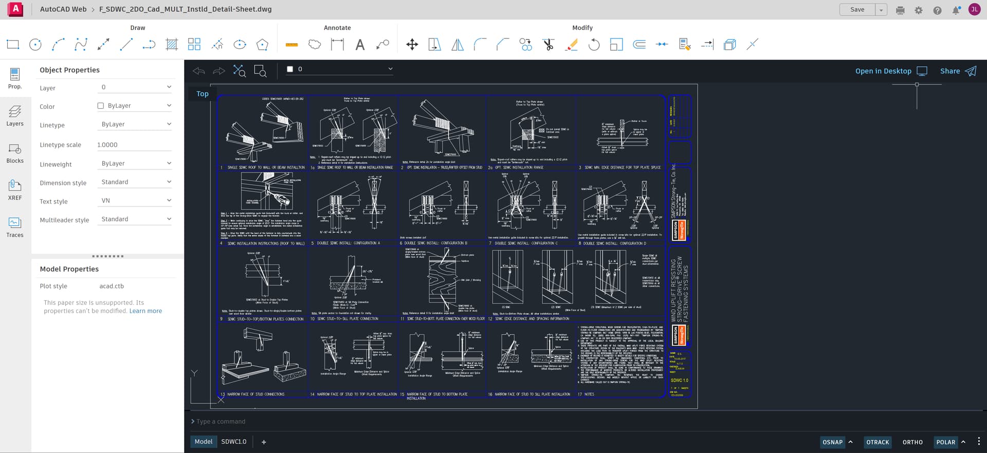
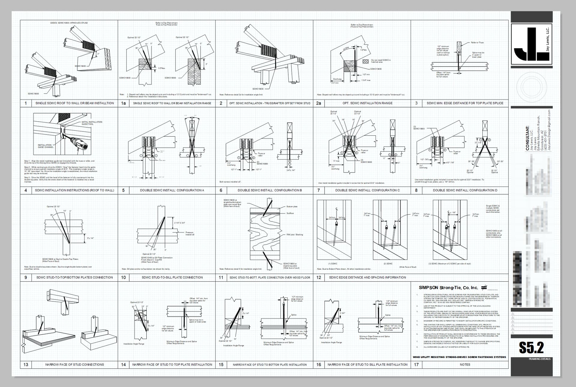
I am building a set of plans and want to insert some details from Simpson Strong-Tie. I downloaded the 2D dwg file from their website. I have tried several ways to get the dwg file into my Layout page.
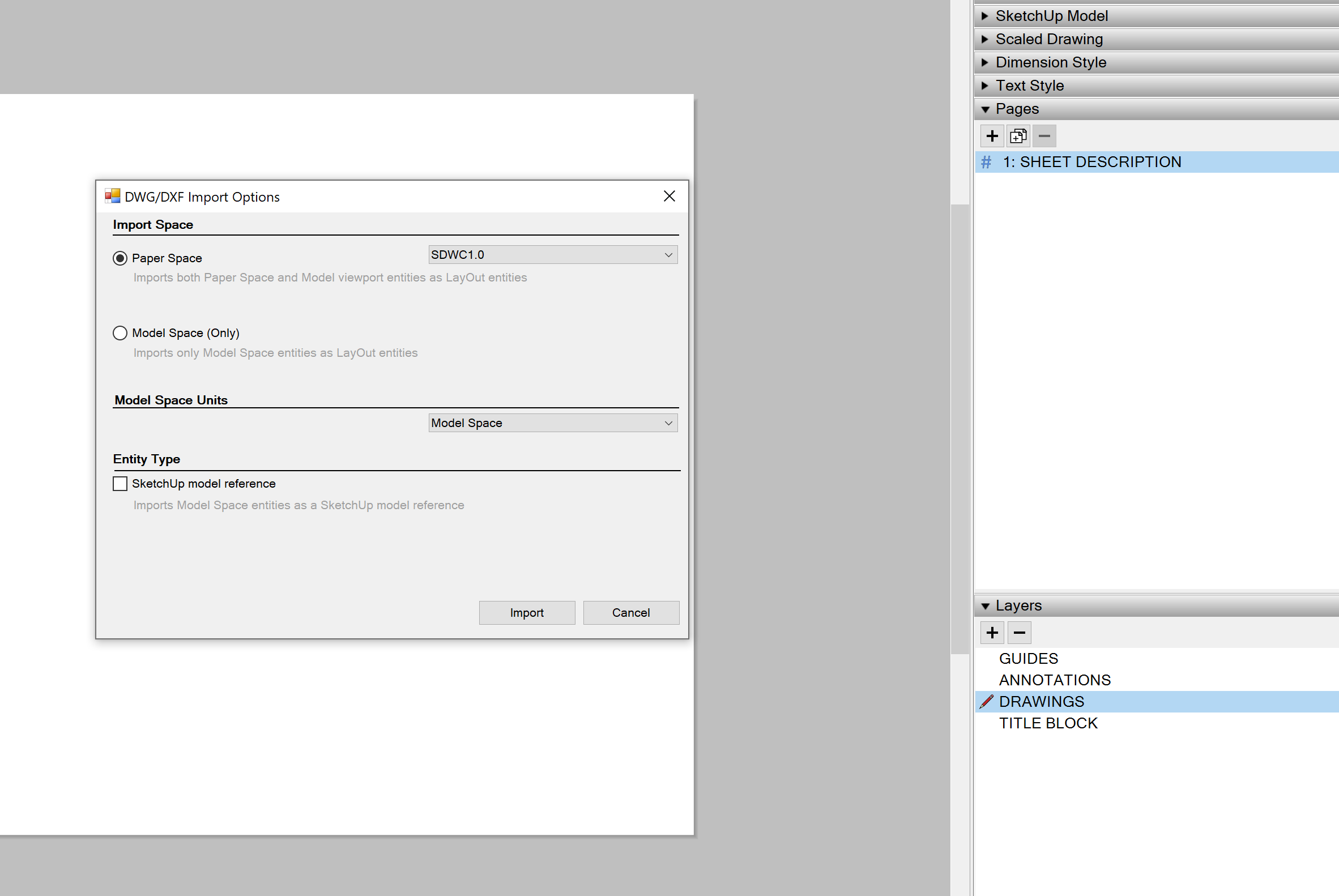
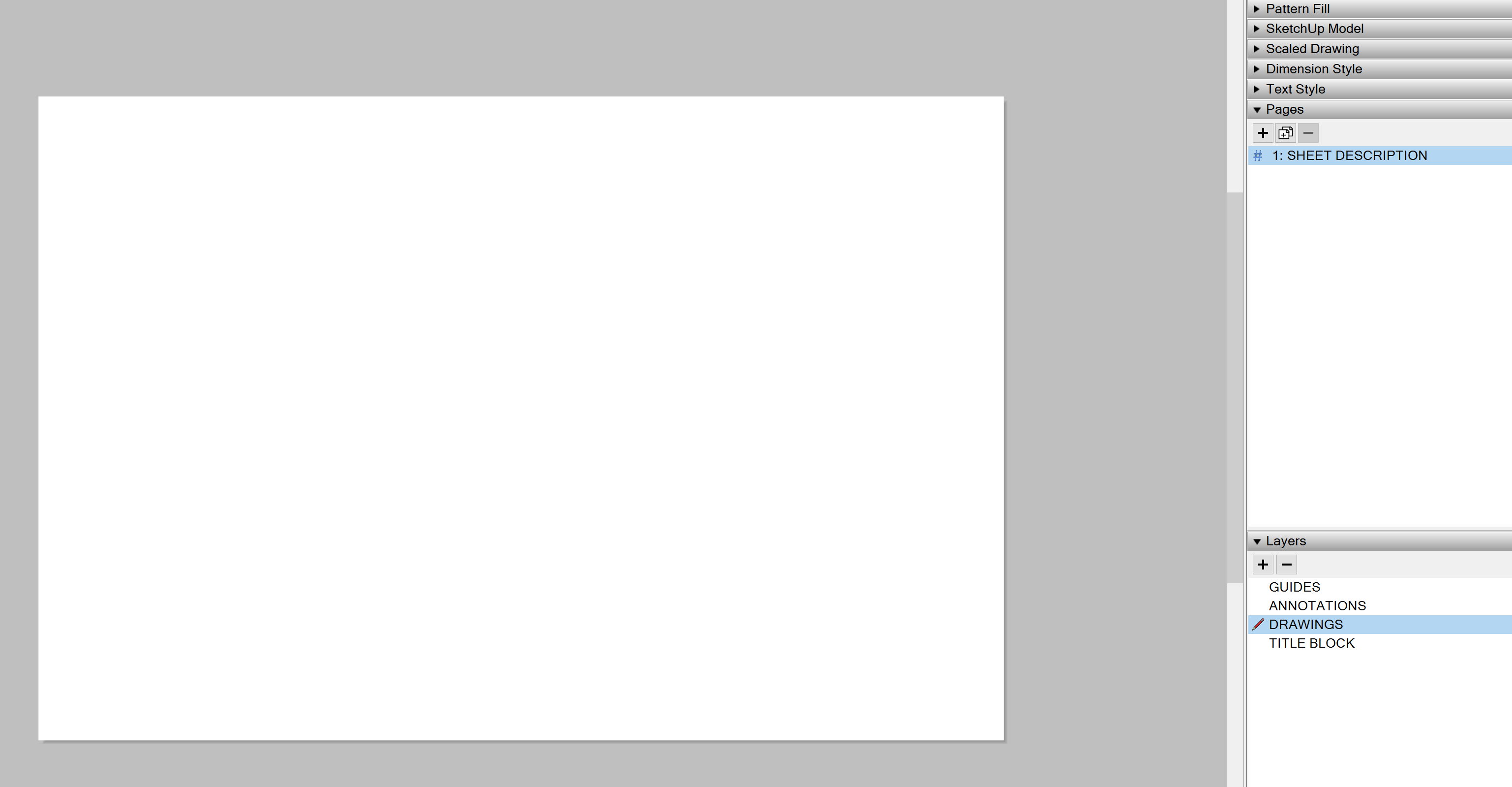
Nothing happens when I attempt to insert the dwg and select “Paper Space” when the option box pops up.
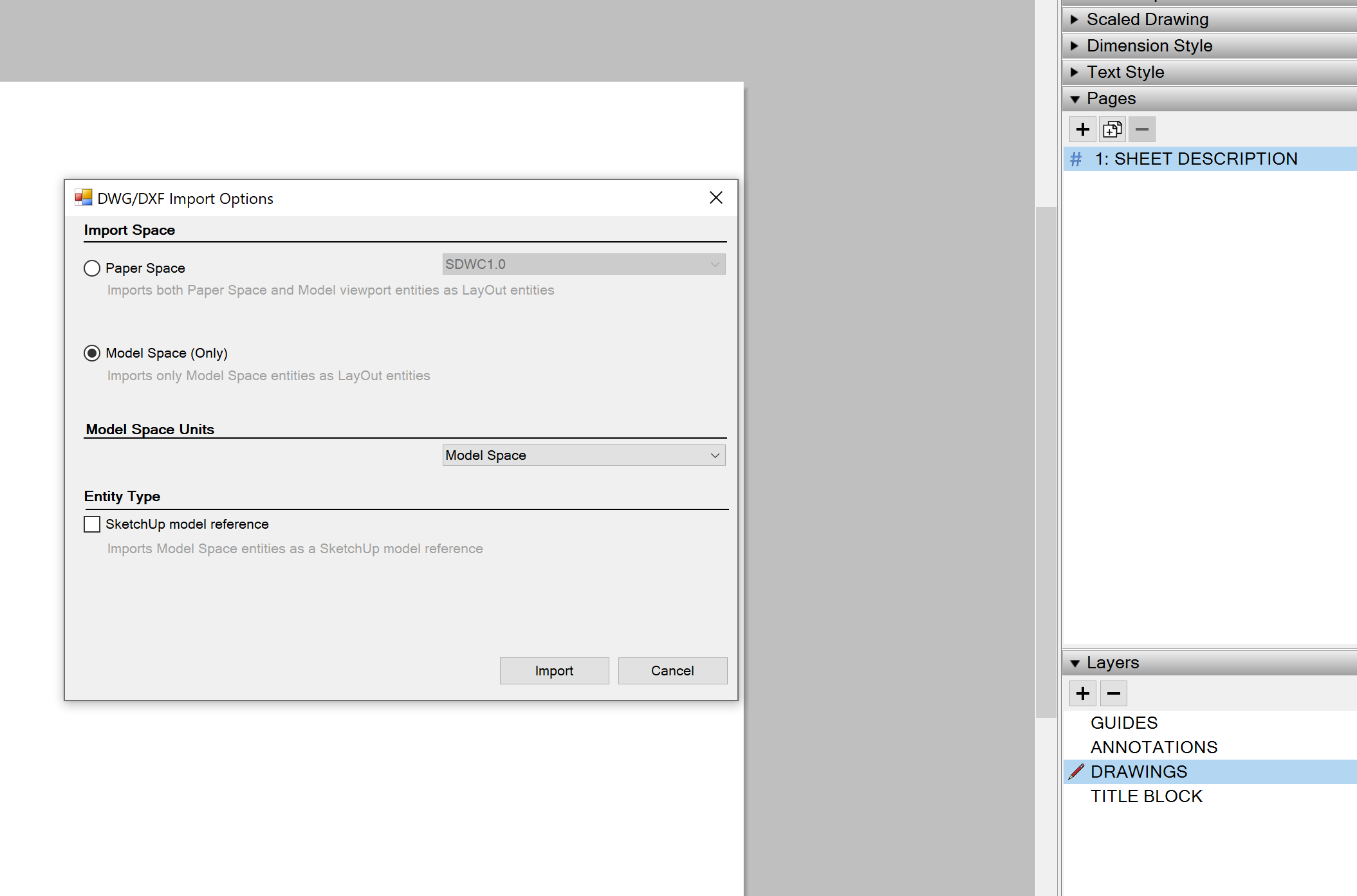
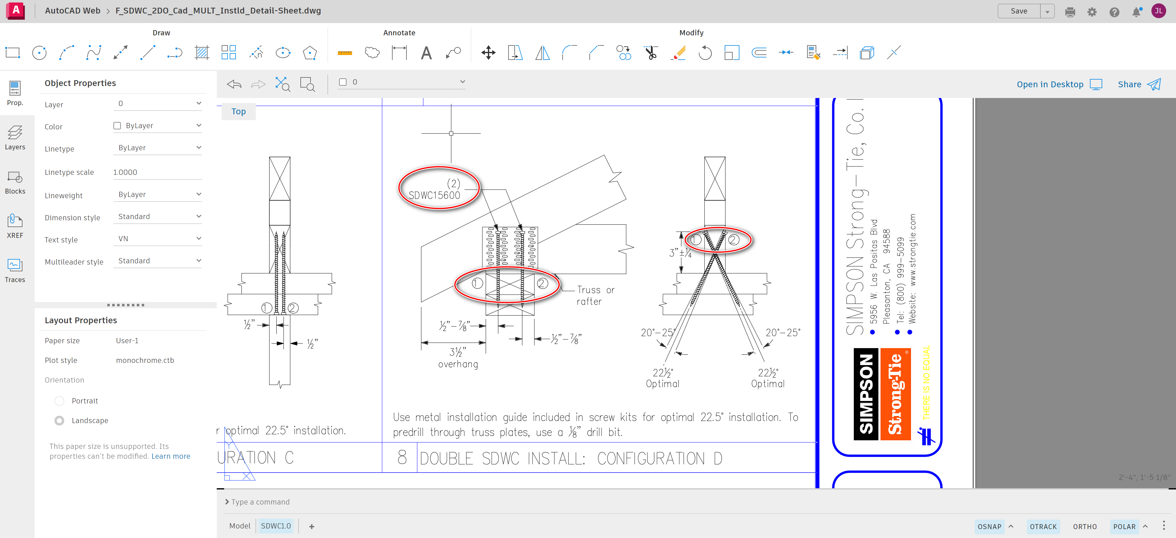
When I select “Model Space” the dwg file opens but it is missing parts and some of the arrows are oversized.
I am able to alter the file and rebuild it but I must be missing something because I am unable to just import a dwg CAD file and add that page to my plan set or insert a cad detail and not lose parts of it.
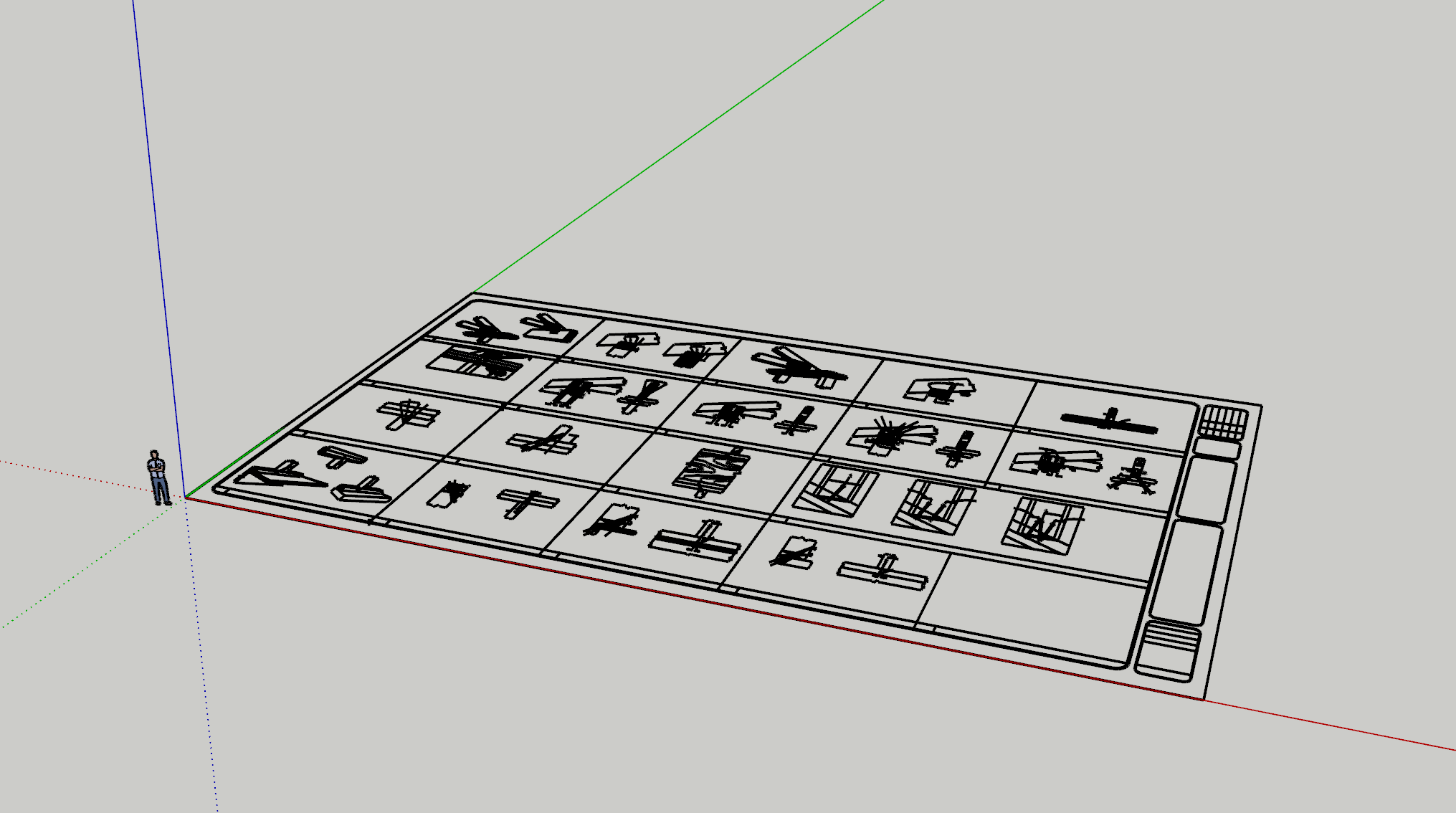
I have also imported the dwg into SU and it also loses parts and comes in huge.
The SketchUp DWG importer doesn’t support text or dimensions so that is why you are not seeing them.
Check your import units in the Import Options.
Checking your units also applies to importing to LayOut. In the first screen, did you check that the imported items are not displayed white?
Can you post the DWG?
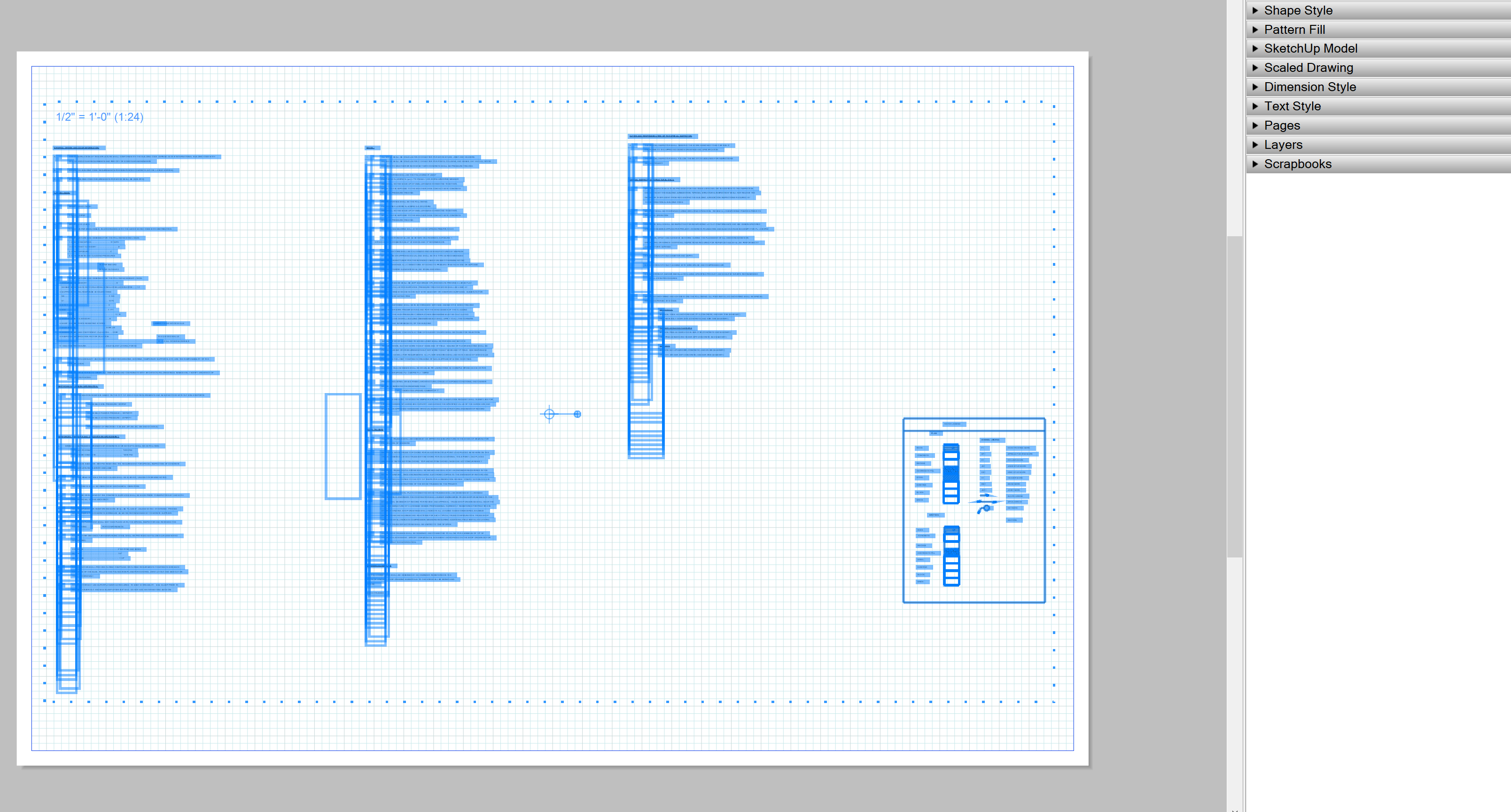
The file doesn’t appear to be coming in as white. I laid down a gray layer and attempted to insert the dwg in Paper Space in a layer above the gray background and wasn’t able to see any insert appear.
I also tried to drag-select the area to see if I could highlight anything that I can’ see.
Hi all, when we insert a dwg the file will come in at full scale then is scaled down to fit to the page and placed into a Scaled Drawing in LO. In this case even though the dwg file shows that there is a PS, the user did not assign a scale to the Paper Space and LO needs a scale to import the PS entities. The Model space scale is 1:1 (good) so LO will then scale the info down to fit to the page. When this occurs, some entities (like arrow heads because this is a defined dimscale in Acad) do not get scaled down as the should.
To fix this, select the imported dwg file (single click) then from the Shape Style dialog, select a scale for the Start Arrow:
I appreciate everyone’s input. I am getting a better understanding of the workflow of dwg, SU & LO.
Is there a reason that the Text and Numbers are altered when inserting the dwg into LO?
I’ve gone through picking different Text Settings to see if the text will pop back to the original size, font, and placement but haven’t been able to find the correct setting. I can obviously manually alter them but I am trying to find the best way to use the dwg in LO.
The texts in your screenshot seem to use AutoCad traditional single stroke SHX fonts. They aren’t supported in other applications and are replaced with Windows fonts.