I’m new to this and I’m having trouble closing all the faces of my object to make it whole. Some lines are missing to close many of the faces so I drew them but now I can’t find the way to merge them to the object so when I try to move it all those lines don’t follow.
There’s not one thing wrong with it, other than it’s sitting at an odd angle out in space well away from the origin.
Modeling is easier if you build the model near the Origin and aligned with the axes.
Right click on the model and in the Context menu that appears, click on Entity Info
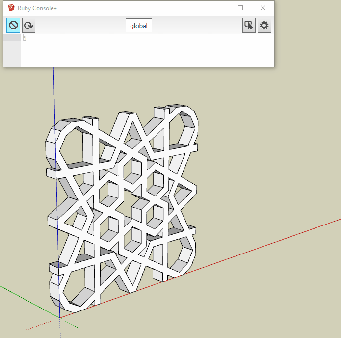
There, you’ll see the model is a Solid Group.
Being ‘solid’ means the model is a closed volume with no holes or stray geometry, like a perfect soap bubble.
Beginner or not, you’ve built a very good model.
The edges you think are missing are merely hidden.
Look to the top menus and click … View > Hidden Geometry and you’ll be able to see them.
Double click on the Group to enter its editing context and you’ll be able to select the hidden edges.
Then you can unhide them via a right context click > Unhide or uncheck ‘Hidden’ in Entity Info.
The reason the new lines won’t merge is because the geometry inside the Group is isolated from the rest of the model.
Keeping things separate and organized is what Groups and Components do.
You need to ‘open’ the Group or Component for editing before you can work with what’s inside the Group.
Have a look at this video to learn more about Groups and Components
The model has been moved to the Origin and rotated on axes.
The stray lines outside the Solid Group have been erased.
I also reset the camera Field of View from ~11° back to the usual default 35° FOV.
Thanks @Geo! Your answer is well detailed and easy to understand for a beginner. I wish this was my model but it is something I found in the warehouse. I’m trying to draw a mould that will allow me to cast this part in metal for a foundry project. I found this thread on the subject: Need to create an inverse or shell of a 3D surface but I would also be interested in anything you might have to add that could help me achieve my goal as smoothly as possible.
But this drawing I would like to use to have a more “permanent” graphite mould machined using the the same moulding process. A two parts mould, one part that has the negative of the cast imprinted in it and the other that is a flat block with an opening to pour the metal in.
So I’m basically looking to create a negative imprint drawing of my part in a larger block of solid graphite.
I started to work on a positive version of the mould with the hope of converting it to a negative version (hollow) afterwards: Star_Tile_12_1-r3.skp (488.0 KB)
There you can see the different elements I will need in this part of the mould like the runner and I will also need some channels between the runner and the part.
Easy like you said! And how would I draw the channels I need between the runner and the star pattern? I tried several things but I can’t seem to find the right way to draw a 3D rectangle channel that fits perfectly between the runner and the shape to mould…
Your profile indicates you’re using SketchUp Make
The Solid Tools @Neil_Burkholder demonstrated are a SketchUp Pro only feature.
They will cease to function when your SketchUp Make 30-Day free trial of Pro expires.
SketchUp Pro’s Solid Tools merely automate native functions common to Make and Pro.
They’re a convenience, not a necessity.
You might find it easier to use the Line tool to draw the shapes on the face of the mold one line at a time.
When you draw a closed loop of edges (lines) on a face, the face within those bounding edges is separated or ‘cut’ into the face outside the closed loop of edges.
With that, simply Push/Pull the face down into the box/body of the mold.
Learn how SU’s Inference Engine enables you to control the placement and direction of the tools.
Hi, Creators-
Finally jumped in to Sketchup and really like its attributes but being a newbie i need some help please.
I am 3D modelling, in scale, a garage renovation into living space. But related to this topic I imported a double hung window but some of the elements while all connected did not reflect the actual or typical construction of a window. Deleted all entities except the two sashes and built a frame and details on them to reflect accuracy. Turns out the lower sash is a component and won’t attach to the rest of the model…the main model is a Group.
Tried right command selecting various, while the lower is selected but options won’t allow attaching to rest of the model.
ideas welcomed and appreciated!!
Isitdav
Further on my previous there are hidden elements used to construct the lower sash that are too many and in error for the correct geometry so will erase the lower and copy the upper to replace. Getting rid of this separate component may solve…your thought?
BTW, it is not a dynamic model.
The 3D Warehouse is an invaluable resource but is still subject to caveat emptor:
ca·ve·at emp·tor
ˌkavēˌät ˈem(p)ˌtôr/
noun
the principle that the buyer (SketchUppper) alone is responsible for checking the quality and suitability of goods before a purchase (download) is made.
A bit of rejiggering is sometimes necessary to make a downloaded model useful/functional but it’s almost always well worth the time and effort. Hope you find this applies to the window model you describe…
Indeed the case with the window. Steep learning curve but a worthwhile challenge!
There here were over 130 elements during deconstruction…
Onward into the abyss of elemental design.
Or not…
Not so easy after all! ; ) I don’t know why but I can seem to properly intersect both items. When I try to push/pull through the face of the mould it doesn’t cut the surface but the shape comes out at the back anyway. Any idea why? I tried to intersect with selection and it doesn’t change anything…
Sounds like you have all the pieces to the puzzle but are just not getting them put together correctly. I’ll bet if you review feedback starting at the beginning of this topic including the suggested tutorials you’ll be a mold-modelling pro in short order.
Like @Geo said solid tools are handy but not necessary.
One line of code can save you a lot of time in this case, because on my computer when I followed the advice @whiterabbitdesigncompany the ‘holes’ didn’t come out as separate faces.
Apologies… in the sequence i submitted (add to rectangular face) once the geometry is on the new face I select all and used “make face” plugin to fill/unify the geometry. Alternatively you can use the pencil tool to do this on a hole by hole basis but takes longer. This is only a method to avoid solid tools if they are not a part of the program (trial or make?). As always, there are many ways to achieve the same results in Sketchup which often depend on personal preference, knowledge and habit!
I’m putting together a model for a mobile store built in a truck and I’m having a hard time finding how to actually insert all the doors and windows into the structure of the back box. Now I just placed them on the surface but how can I pierce the surface to put them in place?
My model is apparently to big to upload here. (9 Mo)