Modelling Kreg pocket screw holes and screws

Hi John,

Before I launch into the details, I want to take a minute to acknowledge your efforts and others in this community. SU is a great software application, but it is not perfect and probably never will be. The real strength of the product comes from your (and others) tireless efforts to help other users, and improve the product. Well done!

I followed your advice and downloaded a new copy of “Kreg pocket hole and screw head v2014” (from 3DW). I then imported the component into a new SU file. And the DC aspect worked as expected (option to remove screw head). Followed up by downloading (from 3DW), “Kreg pocket hole and screw DC v2014”. Tested DC aspects (three screw lengths), all worked as expected.

Being a new SU user, I am still uncertain about the difference in downloading a component from the 3D Warehouse and inserting directly into the SU file, or downloading/saving as a file, and then using the SU import command. Obviously, in this case, it makes a significant difference, import worked, direct insertion did not. I read many testimonials, watch videos, where the majority claim direct insertion is the preferred method (saves time). I will continue to be mindful of this behavior as I gain more experience.

2 Likes

Hi John,

A small point, indeed (pardon the pun)! In the component, “Kreg pocket hole and screw DC v2014”, the dynamic screw length options (see image below) are:

30mm (1 1/4")
38mm (1 1/3")
52mm (2")

The Kreg catalog (see images below) list these screw lengths:

32mm (1 1/4")
38mm (1 1/2")
51mm (2")

Seems to be some differences. :slightly_smiling_face: Not sure if you intended to match these standard Kreg sizes, and if not I apologize for wasting your time reading this. For my present project I am including a cut list and accuracy (including standard off-the-shelf-parts) was important. For reference, I did measure the actual screw lengths (see image below), accuracy limited by resolution. I realize this level of detail will not be important to many, but for my present project I needed to be as accurate as possible. These minor inconsistencies aside, your components have improved my workflow considerably. Keep up the good work.


image

First, I’m very glad you’ve got it working for you. And that to enable that, you prompted me to check the Warehouse models.

Second, the difference between opening a saved component and importing it, is that (as Box said above) when opening, SU views the component as if ‘open for editing’. Whereas importing sees it as a single whole component from the ‘outside’.

And you want to see the whole component from ‘outside’, whether it’s a DC (dynamic component) or not.

You can explode the component without the screw if you want to make it part of the board you fit it in.

Good luck with your modelling.

J

Several related issues here.

  1. I drew the screws originally in a metric (mm) template, though we buy them here in inch/fraction sizes which I remembered seeing on the screw packets, and converted to the nominal equivalents in metric, which are actually very close - less than a mm difference at max.

  2. I had repeatedly to re-set-up the top level DC after saving it and finding I’d lost the ‘wrapper’ somewhere in the process of highlighting the DC and using R-click Save As to save it as a ‘wrapped’ rather than ‘open’ component, then opening it again and using File/Save As/ version SU2014 to save it without the wrapper, then opening it again in SU2014, having to remake the top level DC, before using component Save As… again. At some point I had a typo which I now see, where I typed 1 1/3" instead of 1 1/2". That I can and wiil easily fix though probably not tonight - just home from a long and very pleasant but tiring day with my brother, sister in law, nephew, niece in law and a cousin.

  3. The metric/inch conversions are close but not exact. And I wrongly remembered (and used) 2" ~= 52mm. The Kreg catalog says 51mm/2", which when I think about it is of course right (50.8mm is the exact conversion = 25.4mm x 2).

  4. Small errors in the drawing have crept in on top of the approximate conversions. That too I think I can easily fix.

So thank you for spotting the discrepancies - I was using the components more illustratively than as totally dimensionally accurate representations, initially for my own use. It wasn’t until I saw your posts that I tried the older versions I’d made and put on the Warehouse, and found they weren’t as easy to use as they should be for anyone who uses them more than I did.

And thank you for your patience in sticking with me in spite of the difficulties you had. Useful to me, if frustrating to you. The end product will be better as a result!

I’ll post again in this thread tomorrow when I have all the issues fixed.

Best wishes.

I think I’ve fixed all the issues you identified, and a couple of other small ones I noticed.

I’m reposting here the unchanged version of the plain pocket hole, and the corrected versions of the two DCs - one with just the hole and an optional screw head, and the full one with three lengths of screws. They are now the correct (metric) length, within 0.2 mm of the nominal inch/fraction dimensions. I’ve also corrected the two mistakes in the drop down list of screw lengths - 1/3" corrected to 1 1/2", and 52mm corrected to 51mm.

They are all saved back to v2014, but I’ve left that out of the file names to give a cleaner listing in Outliner and the Component Browser.

Kreg pocket hole.skp (33.3 KB)

Kreg pocket hole and screw head.skp (48.4 KB)

Kreg pocket hole and screw DC.skp (153.7 KB)

Try them out - as before, import them, don’t just open them.

Once we are both happy with the revisions, I’ll re-upload all three versions to the Warehouse.

Greetings John,

Tried the new versions in the above post, the changes look correct. As you point out this increased attention to detail will probably go unnoticed by many whose primary use will be illustration. But,
maybe a few ■■■■-retentive/OCD folks, like me, will applaud your precision and sing your praises. :joy:

I now understand your motivations for creating the components, illustration. So, my comments seem to be quite out of place and unnecessary. And on the surface, my interest in creating dimensionally correct models seem to be a bit excessive. Some background may help. I have turned a simple project into an educational exercise for a family member. She has now developed a voracious appetite for woodworking and specifically in “pocket hole joinery”.

Couple of additional points she made may or may not interest you, but I will forward them, since she is holding me accountable. :grin: As you know, the screw length decision is made based on the material thickness. When setting the Kreg jig for the proper thickness, the pocket hole is located on the surface accordingly. This assures that the screw will break out in the center of the material and penetrate fully into the joining material (see image below). This sample material is a 2"x3" stud. Your component is on the right and another author’s on the left. I now understand why other 3DW models simply provided a series of pocket holes with different insertion points. She also noted that the length of the surface oval is 1 9/16" (40mm) according to a Kreg manual she is presently consuming (image below).

Wait, is that a drill I hear in the garage. :wink:

Again, thank you for all your hard work and help. I have added quite a lot to my SU knowledge base with these discussions.

Good and extra info, Claire.

I’ve only made use of Kreg screws and pocket hole joints a few times in simple softwood constructions for stage scenery. Our wood thickness is almost always 7/8" (22mm) thick, and I drew these holes for that thickness.

I will now check if the screw hole does actually come at the right position in the thickness for that size of wood. And also check the length of opening in the board face. I copied the geometry, then simplified it, from another author, and the angle or hole size may not be quite right.

[You quote from the manual that the jig uses a 10mm drill, but I’m sure I’ve seen an 11mm size too, and I remember we bought a wrong sized drill for our theatre workshop jig. I’ll check tomorrow which size hole our drill makes.

And a 3/8" drill is almost 0.5mm smaller than 10mm. I think the Kreg one is actually 10mm if I remember correctly.]

And maybe I could add a DC parameter for the board thickness which would position it at the correct distance back from the edge, and with the appropriate length of screw hole to reach the edge.

One of the things I emphasize in my modelling of small components for woodwork modelling is using as few faces and edges as possible to give a ‘good enough’ appearance. More just bloats the model, especially if you use a lot of them. That’s why I re-drew the hole cylinders, with only 12 sides instead of the default 24.

The same is true for furniture used as ‘entourage’ in larger scale architectural models. Almost all of the furniture models on the 3D warehouse are totally, grossly, overdetailed for that purpose. I even wrote a topic about it a few years ago.

Have you a link to the Kreg manual you have been quoting? I think I ought to read it.

There’s more to using these things than I had first appreciated.

Well, with a small fudge that no one will normally notice, I’m managed to correct the dimensions, location, and hole size of the DC with screws for a 7/8" 922mm) board.

I found I had drawn the pocket hole only 3/8" diam (9.5mm) instead of 10mm. And not got the screw hole deep enough in the board, even for a 7/8" thick board.

Correcting that enlarged the length of the hole in the top surface of the board, but only to 38.6mm, with the hole at the designed angle of 15°. So I fudged the length by moving the extreme point of the hole 1.4mm along red. That adds two triangular faces to the hole, which otherwise had quad faces. Unless you have hidden geometry turned on, you can’t see this, and I can’t think of another way to get it any better. And two faces extra doesn’t bloat the component by any significant amount.

Not yet updated the model in either this post, or the Warehouse.

Still thinking about how to adjust the DC for different board thicknesses.

Where did you find the manual which shows the hole dimensions? I’ve looked on the Kreg website, and tried the manuals for K4 and K5 jigs. I don’t see those dimensioned diagrams in either.

Which jig have you?

I realise that our own jig may not be a Kreg branded jig, but it looks very similar to the Kreg K4 in principle.

We are using the K5.

The manual that shows the hole dimensions is actually for the Kreg Micro, but the image has dimensions for both the standard and the micro. Not sure if I saved the link, but here is the PDF.

Kreg Micro Drill Guide Instructions (NK7809).pdf (562.3 KB)

And the manual for the Kreg K5

Updated Kreg K5-K5MS Manual (NK8814).pdf (4.4 MB)

The drill bit on our K5 is 3/8", just like the diagram. The text associated with the diagram says 3/8" is 10mm. But when I do the conversion of in to mm, I get 9.525mm.

Looks as if what should happen is that the screw hole goes deeper in the board, and therefore that the pocket hole cutout should be higher relative to the component origin and further away from the edge.

The Kreg K4 jig offers five (actual, not nominal) thicknesses.

  • 3/4" (19mm) (US 1" nominal)
  • 7/8" (22mm) (UK 1" or 25mm nominal)
  • 1" (25mm) (US 1 1/4" nominal)
  • 1 1/8" (28.5mm) (? nominal size)
  • 1 3/8" (35mm) (UK 1 1/2" or 38mm nominal)

That means, I think, drawing several depths of pocket holes and hiding all except the one for a particular board thickness, and having a different guide point for each board thickness, also hidden for all except the current thickness.

Thicker boards aren’t explicitly catered for.

I’ll see how I get on with that over the next couple of days - v busy tomorrow, so if I don’t get it done tonight, it’ll probably be Wednesday before I do.

Here are two links that may be helpful:

https://www.kregtool.com/page-elements/pocket-hole-machine-efficiency.aspx

And one more:

Many thanks, that helps.

I hadn’t been sure if the screw hole goes all the way through (as I have recently been drawing it) or as I now see, should stop slightly short of doing so. That helps.

Is the ‘family member’ your daughter? What is she drawing, then making? Just curious - ignore the question if you want to.

On another tack, you / she might be interested in the plugin I helped Steve Baumgartner to write, available from SketchUcation.com/pluginstore
Wood Framing | SketchUcation

And possibly the updated Angular Dimension as well.

I don’t have any religious feelings about Kreg pocket holes. But I’m getting more familiar with using them in practice at our theatre workshop (www.abbeytheatre.org.uk).

Many thanks for your enthusiasm driving me to do better with the components.

Starting to get the idea that this topic is one of science, or maybe religion. Kreg zealots are a very vocal group. But the more I use the system, the more I understand the enthusiasm. :smiley:

She is making a cabinet for toy storage (almost finished). And she is now working on a shelving system for garage storage (my idea).

I just edited my previous post, as you were typing. Have a quick look back.

Thanks, will pass the info on. Her questions are getting more advanced.

I’ve drawn the geometry for the DC, but not added the Dynamic Attributes yet.

And also added a 2 1/2"/64mm screw.

After a GREAT deal more fiddling about than I expected or wanted I’ve now got two versions of the Kreg holes, screw heads and screws working. and saved them as v2014 components.

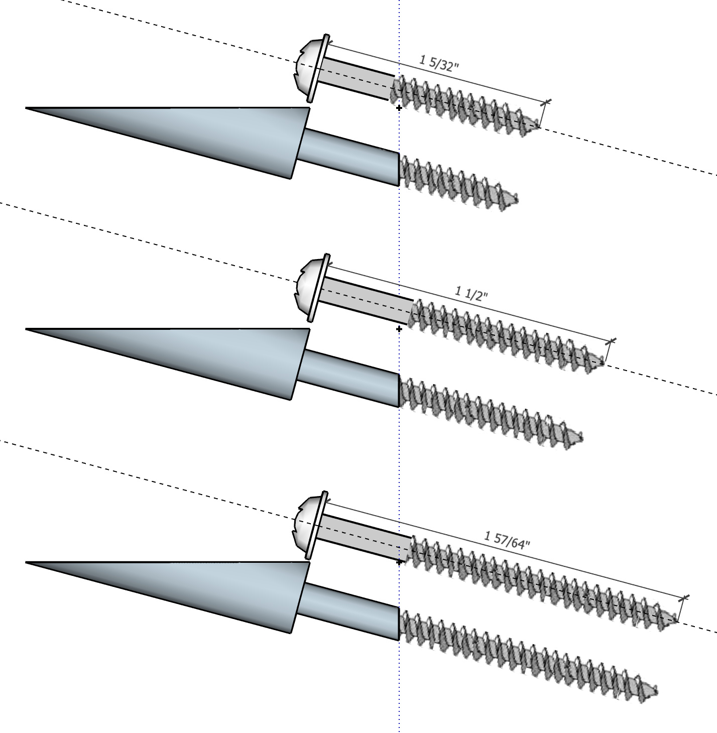
The first is the DC version based on the drawing above. I’ve added the 2 1/2" screw length, and the DC has options for the thickness of the board as well as screw length.

[And now when thought I’d done, I see that one hole in the DC has reversed faces - white outside, instead of inside - another size has two overlapping hole sizes, and one board thickness is missing the hole altogether. And the screw hole sizes are 3mm diam and should be 4mm for no 7 diam screws. Very frustrating.

GRRR. Will fix and re-upload the model, but not tonight I’m afraid - it’s almost midnight here in UK.]

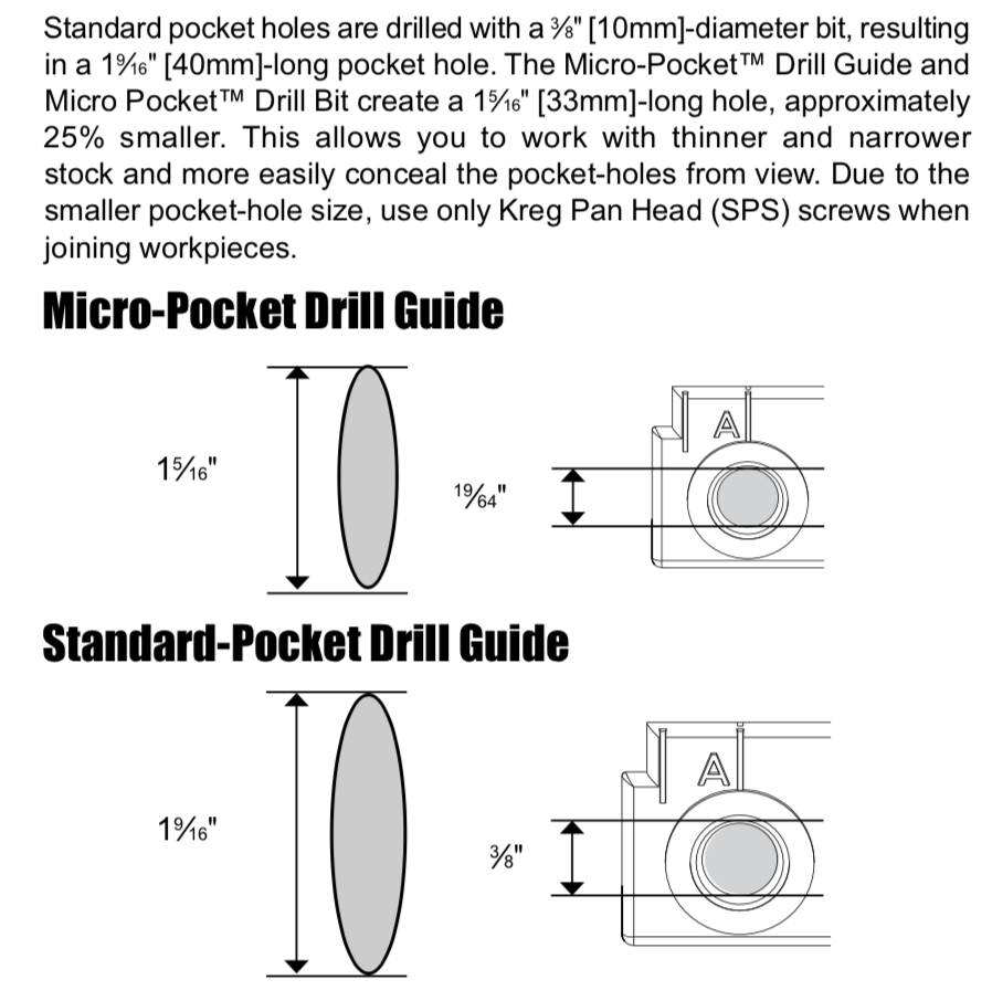
I cannot get the geometry to give me a 40mm length for the oval hole in the face of the board. With the designed 10mm hole and 15° angle, the opening is 38.6 mm (= 10/sin(15°) = 10/0.25882) , not 40mm. I could fiddle it by moving the outer ‘point’ of the oval away from the edge by ~1.4mm, but this distorts the hole and adds two faces to the geometry. Kreg have approximated here in their manual.

The second component has a version of the pocket hole for each thickness of board, includes just a screw head, not a full screw, and is not a DC.

Kreg pocket holes and screwheads.skp (369.0 KB)

Each pocket hole and screw has the properties Glue to Any, and Cut Opening. This was incredibly fiddly to get working. I’d set the properties, close the edit, and find that the opening was not working. Eventually settled it by several times exploding the component, and recreating it from its subcomponents. Even when both the top level and pocket hole components were both showing Glue to Any and Cut Opening in the Edit tab of the component browser (in v204), the opening would often stay stubbornly closed when reinserted into the board. But once I got it working, it stayed working (I hope you find the same!).


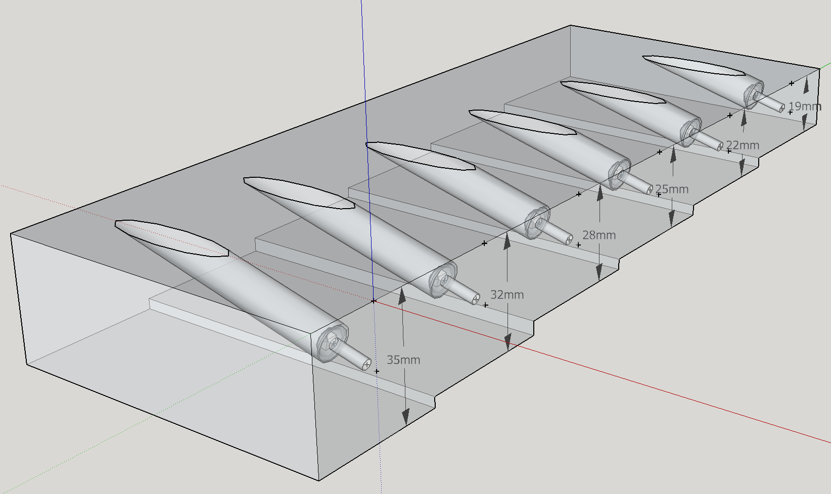
After importing this component, you might well want to explode the board, and delete the board faces and edges, leaving you with six separate components, one for each board thickness.

Drag the size component that you want from the Component Browser, and align the insertion guide point with an edge and with the mouse hovering just a little away from the edge over the face you want to insert it into. Too far in, and you’ll lose the edge inference. Too little, or over an adjacent face, it will Glue To the wrong face.Then click to position the hole.

You may need to rotate it in the plane of the face to position it correctly, depending which way the edge is oriented.

If you explode the inserted component twice you can merge the hole geometry with the board, but keep the screw head as a component. Hide the screw head, delete it, or turn off the layer (tag in v2020) so it doesn’t show if that’s what you want to do.

By design, the screw hole cut by the Kreg drill doesn’t go all the way through. But if you want to show where the screw hole will emerge when the screw has gone in, the guide point on the vertical face (in the image) is the centre of what will become an elliptical hole. Draw a circle there, and scale it vertically to make it elliptical, if you want that level of detail.

TBC tomorrow

2 Likes