As my first How To post, here is a method of creating a component that cuts through a surface.
Here are a few things to keep in mind
Although you can activate the cutting feature on an existing component, it can become a complicated knowing how it will cut. In this example, the cutting component will be created independent of any design project.
Create a surface that will be serve as the location of the cutting plane for your component and the drawing plane from which your component will be created. It won’t matter if it is a ground plane or a vertical plane as the component in this example will automatically align with ANY surface. *Be sure that it is larger than the component.
Draw your component on the cutting plane surface. The area utilizing the cutting plane must stay within the bounds of the cutting plane surface.
Select all the geometry making up your component. Make sure the cutting plane is not selected.
Once selected, go to the menu bar and select Edit > Make Component. The axis in the component preview should be flattened and laying against the cutting plane.
In the component creation dialog, “Replace selection with component”, Cut Opening and Glue to: “Any” should be selected.
Provide an appropriate name … and then select Create
Your component should now reside on the cutting plane and you should be able to find it in the In Model area of the Component Browser. (Window>Components). You can now save it to your local component library and or upload it to the 3DWH for use in your future projects.
Here is an old video (SU 6 I think!) running you through the steps
Howdy CD,… and just drew a 4 pain fold out window and followed the steps. I have in my library now…cool. One thing to add that I got from watching Matt Donley (MasterSketchUp tutorials) is to make the drawing plane a group right from the get-go. Then draw your component on it and this way only the component will be selected, being you would have to include the plane on purpose. It does, the window, automatically alines to the face you select and with multiples, using inferencing to line or square them up.
I was tracing a imported CAD floor plan earlier and realized the time saved by just using rectangle instead of line tool for tracing the walls. Especially that E (erase) and R (rect) keys are side by side. So popping out the extra line is cake and the inner and outer are done together. MUST ALSO ADD, I used the inferencing feature to match up walls and did not realize the extent of it. I could lock on to a point on the other side of the building and go through two walls to aline them together, plus another one matching a inner wall. I had 3 different points referenced to alined a closet wall, WOW… I spend along time pulling out my hair learning and making mistakes. It is coming together finally and with the addition of info like yours and others. Plus individual`s willing to share an explanation. I am not looking for someone to do it for me, I learn from my mistakes and would like to know why it failed. Not how to do it right the first time if that makes any sense-!!-?? Any how THANKS for sharing and it will help out more then you will realize…Peace…
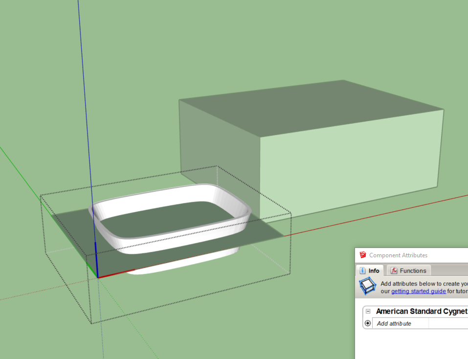
I have tried to create cutting components several times without success. My latest failure is attached. What am I doing wrong? I have watched countless videos, all of which show that this should be easy. Is it something to do with the fact that the object I am trying to turn into a cutting component doesn’t have square edges? On the left of this model you can see the original non-component of the basin sitting in the cutting plane I created. On the right you can see how the component doesn’t cut through the surface of the box I’m trying to put it on.
currently you have the cutting or gluing plane set at the bottom of your basin, so on insert it glues to the surface. The axis needs to be positioned at the desired height or depth,
make the intersection a group, delete its surface and inner geometry if there is any, hide this outline, then cut and paste in place the group into the basin component, then explode the group. this will give the loop that the cutter can use
This component is very detailed and large in file size, would you consider making a lot smaller with less faces?
Plus since you have Pro and if you simplify the model a dynamic version that can do multi cuts at specific depth/face is possible, can show how if you are interested
Thanks so much for your fabulous instructions! I would love to know how to do the dynamic version if you have the time – very much appreciated. Cheers, Mark
I meant to respond to your question about simplifying the component. Yes, I downloaded this from the 3D Warehouse and I notice that it is much more complicated than I need for my model. As far as I can see there is nothing in Sketchup Pro that does that natively – how would you go about this?
Hi folks. I am feeling like a complete failure!! What on earth am I doing wrong adding a cutting plane to a component??
I tried doing everythingSuggested by pcmoor, but I couldn’t get that to work with the component I was using the downloaded from the 3D Warehouse. In desperation I downloaded another component and tried again.
Here is what I did:
I downloaded a component from the 3D Warehouse
I exploded the component
I selected all of the parts of the model and aligned them so the axes pass through the model 64 mm below the top of the model (where I want the cutting plane to be)
I drew a flat surface at 0 on the Z axis, passing through the model
I selected all of the pieces of the model (but not the flat surface)
I right clicked the model and selected “Make Component”
I gave it a name (American Standard Cygnet Basin), selected “alignment with horizontal surface”, selected “cut opening”, and saved the result
I selected the new component from the Components dialogue and drag it onto the simulated cabinet on the left
I think the part you are missing is the cutting loop. This is needed when there isn’t a specific edge in your model that works as the cutting plane.
I made my own sink as I’m on 2017 so not able to access your model.
But you can see the process here.
Note I’ve used Cut and Paste in Place from my context menu, you wont have those there, they will be in the edit menu.
I am trying to create my first cutting components, but not having a lot of luck getting the desired result. My goal is to embed a set of small displays into a wall covered in wood slats so they’re flush with the surface, essentially cutting away the wood slats. I would love to be able to move the displays around without changing the wall geometry for now, and a cutting component seems like the right route until final placements are determined.
I have a simple extruded rectangle here to represent the small display I want embedded. I want to move it into the wall and cut away the slats.
I tried creating a cutting component using the method @Box so graciously illustrated, but not getting the results I want. I think I’m setting the axis wrong.
A cutting component can only cut one face. I assume the fronts of the slats are in the same plane. But these fronts are all different faces. You may need a plugin that uses your component to cut through multiple faces, not a “simple” ‘Cut Opening’ component
The videos in the OP are no longer available here. Are they accessible anywhere else? I ask because I have a lot of difficulty successfully creating a cutting component and must be doing it wrong.
The easiest way to create and also to understand a cutting (therefore it must also be a ‘Glue to’ component) is by creating a rectangle and in its perimeter a second rectangle on the larger rectangular face. Select the smaller rectangle and its little face and make it a component. Be sure to tick (for instance) ‘Any’ and ‘Cut Opening’ when creating the component. That’s it.
You can now edit the component (deleting its little face) and add and adjust anything in the component, leaving its gluing plane where it is, the blue axis marked by the blue cross.
It’s not so much that I cannot create a cutting component. It is more that oftentimes when I do, it doesn’t do any cutting. I know that there are some rules such as only having one face to cut and that it can only cut raw geometry.
The commonest example of this is using a sink component to cut a hole in the top of a work surface. So I create the sink component, make it glue to a horizontal surface, and select the cutting option. Then I go to my group of kitchen cupboards and open it so that I am looking at raw geometry. Then I try to import the component and set it in the worktop. Even when the cupboards are just plain boxes, the sink won’t cut a hole. It’s not working the way I expect but I am sure that is because there is something I must have overlooked.
Judging by the number of people flummoxed by this on this forum, there must be something unintuitive about it.
The important thing is that you have to have a closed loop of edges (raw geometry) at the red/green plane of the component. The easiest way to proceed with it is the one proposed by @g.h.hubers
The cutting component:
The loop of edges without its face (or even more than one loop if wanted) and the gluing plane (the local red/green plane marked by a blue cross) must be coplanar in the first place. Anything else in the component is irrelevant for now. The sinks perimeter could be that loop.