I need to expand the bottom shelf of my cabinet out to the sides, which, hopefully, you can see are on an angle. I’ve made components of the front, sides (one component), and the bottom. Thanks for your help in advance.
First, make the rail cross piece and the bottom into components.
Open the bottom for editing.
Draw a short vertical line where the bottom meets the front of the bottom rail.
Push pull the right side front face this creates to meet the left-most part of the side.
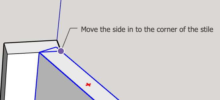
Select the front vertical edge of the bottom, and Move it along the red axis (tap R-arrow to force the move on the axis) to meet the side face.
Thank you, John. You are obviously familiar with woodworking. I’m “spanking new” to SketchUp and Layout. I’m in the process of rebuilding the cabinets in my kitchen. I’m wondering if this might be a skill I can translate into a side business so I’m exploring designing with SketchUp to improve accuracy and efficiency.
You points are well founded. Right now, I’m using this model to confirm accurate dimensions and geometry. The joinery and finer points of finishing I’ll address as I actually construct the cabinets.
Thanks for the follow up, Dave. Haven’t had a chance to work on this part of my model but plan to do so later today. Will let you know if I have any problems.
I used to build furniture professionally (fully retired now). I did all my designs in SketchUp.
One of the great values of modeling thoroughly in SketchUp is that you can exactly model each joint to understand how you will make each one and how they will go together. Much lower risk than discovering issues in the shop!
Don’t know if this is Steve or John, but I did try to eliminate the overlap of the front style and side by using the eraser and it erased the whole side. My plan is to cut the side on the appropriate angle to butt against the front style using pocket joints.
On my cabinets/raised panels doors I’ve been using a combination of Kreg pocket joinery and Festool dominos where appropriate. I did see that I could download pocket joinery in 3D warehouse. There were also biscuits but no dominos that I saw.
Here’s my questions 1) how would I eliminate the overlap and 2) did you include every point of joinery in your models?
Components like Dominos and biscuits are fairly trivial to make and add to your models but, if you are using the model for your own projects, it may not be worth the time to add them.
Getting rid of the overlap: I’d want to see your model as it is now to give you guidance.
As for showing the joinery. For me it depends on the audience. For my own projects I include joinery if it affects the overall dimension of the parts or in cases where there’s concerns about potential conflicts. Or sometimes I just make the parts overlap. For projects I do for clients like the woodworking magazine, I do show all joinery and all hardware such as screws, Dominoes, etc. I do that because the plans may be used by people who don’t have a lot of skill in the shop.
Like @DaveR I don’t know how far you took your model since I last saw it. So, I’ll use the original to show one idea to miter the front corners. Before doing this I changed the axes of the side to align with it so that the bounding box is tight. Depending on material, a miter might be strong enough on its own. Cutting a groove for a spline would use much the same kind of pushpull as I did for the miter. Something like biscuits or dominos would take more work. I’d make a component of one bit, place it between the stile and side, and then subtract it from each. In something like this, the value of modeling the biscuit or domino would be to assure that it won’t cut through the outside.
Don’t know if this is Steve or John, but I did try to eliminate the overlap of the front style and side by using the eraser and it erased the whole side. My plan is to cut the side on the appropriate angle to butt against the front style. I’ve been using a combination of Kreg pocket joinery and Festool dominos where appropriate. I did see that I could download pocket join
That indicates you erased an edge that is required because it bounds a face. Steve shows a good way to create the bevel. Another way would be to move the edge.
If you can model a cabinet you can model a Domino if you want to add them to your model.
Here’s my model. My original question was how to extend the bottom of my cabinet to the angled sides. Not sure if it was John or Steve who responded. I’ve been very busy with my full time job…interesting how this gets in the way of my hobbies, and haven’t tried his suggestion but plan to do so shortly.
As I said, I tried to eliminate the overlap of the side and the front style but was unsuccessful. Also, I would like to show the side butting up against the front style on an angle that is parallel to the front of the style, if that is clear.
As Steve said earlier, first reset the component axes for the sides to get a tight bounding box. (R-click, Change Axes, then set the red axis along the bottom edge.)
Cut the side at the front to make a single mitred edge:
Make the bottom a component. I/you should have done this earlier. It’s picked up some stray edges and an enlarged front face, which I spotted because its bounding box is too big top to bottom. Pulled out to be visible, here’s the problem:
This is partly because I forgot to duplicate cutting out the corner round the stile, and partly because you had stray geometry in the bottom, because ou didn’t make it into a component as soon as you had drawn it. DO THAT, ALWAYS!
The easiest way to fix that is to draw lines on the top in that corner, select the top and cut to clipboard.
The select all (inside the component) delete it, then Edit/Paste in place the top face of the bottom, then pushpull it down the thickness of the base.