Hi all! I am going to be jumping on the live stream to model some more machine parts in SketchUp!
Download the image below and be ready to follow along!
2020-04-08T18:00:00Z
Join me on YouTube, Facebook, or Twitch!


Looking forward to seeing how you do these, Aaron. That last one has at least one incorrect dimension. ![]()
May be it’s an Escher part?
Could be. I cheated and changed one dimension to make it work.
How do the parts go together? What is it used for?![]()
And is it assumed the bores go through? It’s been more than forty years since my maniacal drawing class.
The only one that clearly shows it is the first. I made the assumption that the holes and slots went through but you know what that does. ![]()
Except for the second one the others all appear to be intended for manually drawing section views of the parts.
Yeah, there are letters and arrows that suggest these were either originally accompanied by section cuts or the training intent was to create them at the marked locations.
Dimensions on the first one also seem messed up to me. The front wall should be 20 thick based on the rest (50-30 = 20), but it looks like it was drawn as 10.
Ah yes. Faked out by how the dimension leader seems to go through the outside corner until you look very closely!
One of those things that doesn’t tend to happen with 3D models views in perspective. ![]() I think they could have done something to reduce the chance of confusion for the students these are aimed at.
I think they could have done something to reduce the chance of confusion for the students these are aimed at.
Weren’t you the person who brought up Escher?
Hi guys,
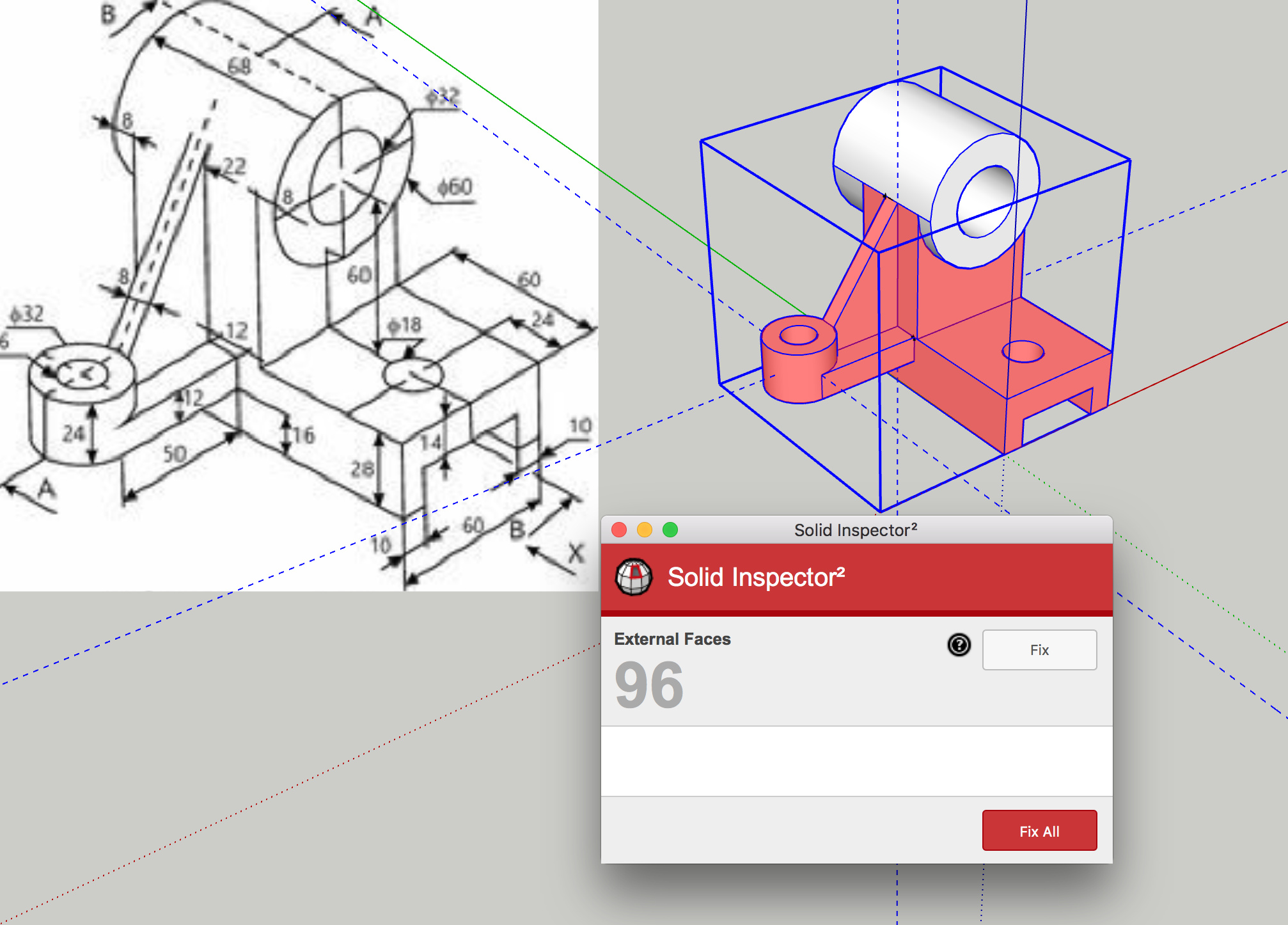
So I’ve been working my way through these machine parts to try and figure them out by myself before the virtuoso steps in and shows how it’s done! I’ve come across this issue with “part e” and not sure where I went wrong… any suggestions as to how I achieved this?!
Screen Shot 2020-04-08 at 17.54.10|690x495
External faces are “flaps” that join the main body of the object at a single edge. I can’t tell from your image how they came about. When Solid Inspector 2 has its report dialog open, press the tab key. It will draw a red circle around an offending bit of geometry and zoom toward it. If that doesn’t make clearer to you what is wrong, upload your .skp file here so we can take a look at it.
Thanks for your reply slbaumgartner, I tried that and there was indeed a red circle! Although I am still none the wiser ![]()
![]() I’ll upload the file and you might perhaps see my errors…engineering parts practice 2.skp (451.8 KB)
I’ll upload the file and you might perhaps see my errors…engineering parts practice 2.skp (451.8 KB)
Thanks guys! ![]()
Here’s my feeble attempt at these parts.

Thanks Shep, Not too sure hw to do that, but I’ll give it a go!


