That’s a nice touch. This would be a handy thing to be able to toggle on/off for drywall and cladding as well. There have been many times I’ve had to build a weird wall assembly (as is my custom), and I end up with lines on the face. It’s a pretty top-tier first world problem, but if it were possibly an easy thing to do, that would be great.


Version 2.1.1 - 05.09.2021
- Added an option for subtractive geometry into the Walls tab of the Global Settings.
- Sub-groups within wall panels can be made persistent and “subtractive” by naming these groups to (subtract1, subtract2, subtract3, etc…)


This is quite a major breakthrough for the wall plugin. I’ve been trying to think of a way to enable (manual) customization of the wall geometry for quite some time, specifically subtractive modifications. This system will now allow the user to achieve that goal.
Naming a group within the wall assembly to include the key word “CUSTOM” (case insensitive) will allow it to persist upon rebuild.
Naming a group within the wall assembly to include the key word “SUBTRACT” (case insensitive) will allow it to persist and boolean subtract from other groups within the assembly upon rebuild.
The subtractive group needs to be a valid solid for it to function correctly and its entity name needs to contain the key word “subtract” or “SUBTRACT”.
What I like to do is create a special tag/layer for the subtraction geometry and then once I am done modifying or creating it I turn off the visibility of the layer/tag and only the holes or results in the wall geometry is shown.
P.S.
The way I’ve set up the naming system will still allow for custom naming of the groups, all that is necessary is to append the keyword “SUBTRACT” at the end of the entity name.
Excellent, this adds an important ability to create more realistic models with your extensions. Plus it reduces the project time by eliminating the destructive final step of exploding the model to add these subtractive entities. 
Yes, I am trying to get away from people having to manually edit or exploding the assemblies thereby rendering the extensions pretty much useless.
If we can somehow build enough flexibility into the system but keep the parametrics it is a win-win for everyone.
Version 2.1.1b - 05.09.2021
- Components within wall panels can also be made persistent and “subtractive” by naming the component instance to (subtract1, subtract2, subtract3, etc…)
Version 2.1.2 - 05.10.2021
- Added logic into the add and draw menus to prevent users from using single and double quotes in preset names.
I apologize I have not been very responsive on the boards lately and updates are on pause for a few more days as I am in the middle of a move. Not something I was hoping for in the middle of a pandemic, but sometimes you just have to roll with the punches.
BE safe. Take the time you need.
Version 2.1.3 - 05.20.2021
- Fixed a bug with pocket doors when using the “No Frame” or “CMU” wall framing mode.
Glad to see you’re back and hope the back is no worse for wear. 
I’m still in the thick of the move but I did manage to squeeze in a few updates and some quality code time. No heavy lifting, at least on the code side the next few days.
Version 2.1.4 - 05.29.2021
- Added an option for vertically offsetting text and symbols within the General tab of the Global Settings.
- Annotation text and symbols for doors, windows, garage doors, columns, Simpson Strong walls, and shear walls can be vertically offset a custom amount from the bottom of the wall.


:'D Awesome!! Great work!! Are these new parameters only added to the wall plugins?
Correct, however I am looking at the electrical plugin next.
Version 2.1.5 - 06.06.2021
- Updated the Medeek Estimator to include lumber/member lengths in both feet-inches (fractional) and decimal inches when using imperial units.
- Further optimized and organized the Medeek Estimator code base in preparation for expansion of its functionality.

Version 2.1.6 - 06.07.2021
- Enabled an option for a steel framing (Cold Formed Steel) texture for lumber/studs in the global settings.


In the 2D mode the steel framed walls will appear a grey color as shown:

I was about to dive into the estimating module this morning but I received yet another email regarding steel framing. This update only provides what I like to call a “cosmetic” steel framed wall. All I am really doing is applying some textures (and hiding one face) to the otherwise standard wood studs so that they resemble a steel stud. These are not proper steel framed walls in my opinion.
This option in the Materials tab of the global settings is somewhat experimental and I am sure further improvements can be made so please send me any feedback, but realize that dimensionally these are not “real” steel framed walls. To take it to that level would probably involved creating an entirely new plugin devoted only to steel framing (CFS).
Please see model here:
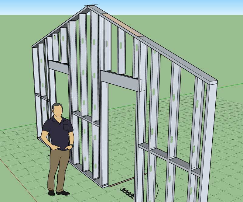
How much more dimensionally accurate does it need to be? That looks pretty neat!
As I look at this, is there an easy way to get the headers to be separated in some way so that they are flush with the wall studs? I know it’s probably one of those “it’s done a million different ways so making it super accurate isn’t necessary” types of things, but I thought I’d throw it out there.
PLEASE don’t make it a priority.
Actually a little bit of logic could separate the double header so it is flush with both the inside and outside of the wall. However, I’m not going to make it a priority unless someone can show me some details or images with the steel headers framed this way, again I’m not very familiar with steel framing.
As far as the programming, probably about 10 minutes of my time, so yes it can be fixed quite easily.
As far as the dimensional accuracy is concerned, steel framing uses a track as the bottom and top plates for the wall. The length of the studs as shown are therefore shorter than they would be actually in real life. Additionally various blocking and bracing methods are employed with CFS systems, none of which are implemented currently in the plugin.
To my knowledge framing up openings does not typically require a “trimmer” stud and headers can be a double channel type member (back to back or a boxed configuration) or a truss like structure. CFS framing is similar but different in many respects to standard wood framing. It is its own can of worms.

What I have here with this “Steel” option is a representational solution at best.