*If other questions arise concerning any of the extensions (Wall, Foundation, Truss and Electrical), feel free to add to this topic. Hopefully a central repository for user questions/answers for the extensions will develop and be of value.
There is a new extension feature called “Subtractive Geometry” (subtract for short). I won’t go into the requirements of using subtract, but details are here:
Since the Medeek extensions are parametric, modifications to the extension models use their own tool set. For instance, there are no wall extension tools to add plumbing to wall assemblies. Subtract allows for non-extension geometry to be added. Subtract basically masks the additional geometry. This prevents the added geometry from being deleted after a regeneration command in the extension (eg. after edits using extension commands).
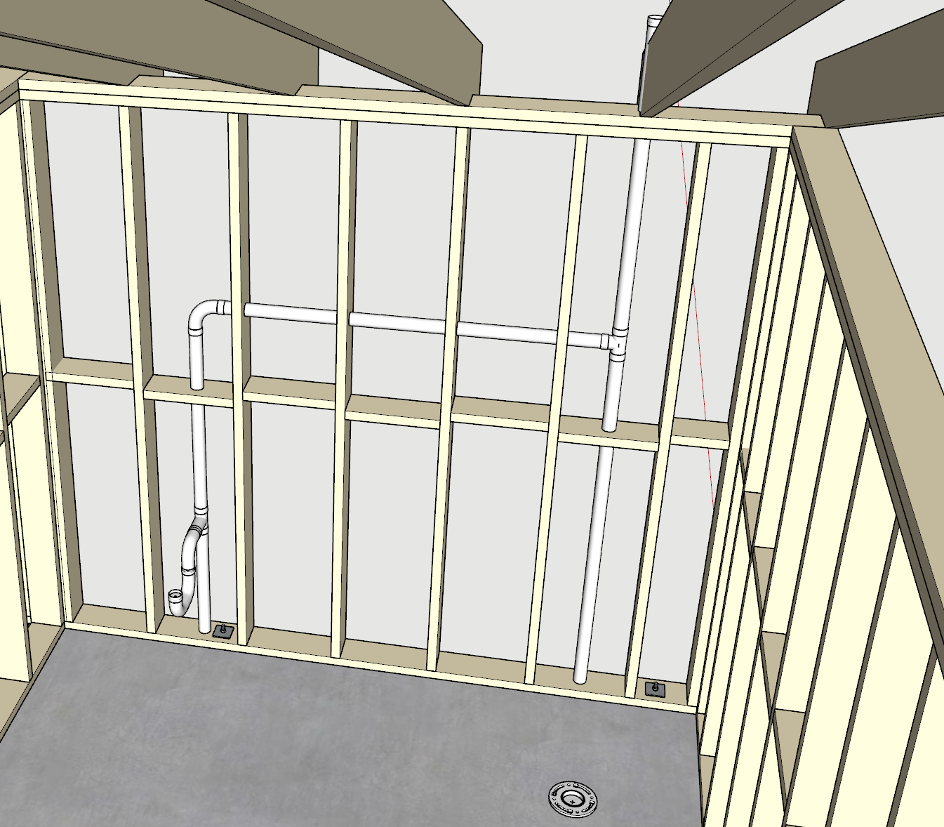
In this example plumbing has been added to the wall assembly (image 1,2). The plumbing geometry (solids and instance names include the keyword “subtract”) will create voids in the wall geometry (image 3). The question is how to add the continuing plumbing geometry, that has been added to the wall assembly, to the foundation with appropriate penetrations (like the closet flange, image 4&5).
As always, thanks for your help.
One approach that came to mind as I prepared the post, was to separate the pipe geometry at group boundaries. One section would be in the wall group, the other in the foundation group. The demarcation line would be the lower edge of the bottom plate member. And the next post was about perpendicular wall segments. This method could also be used in this scenario (images below).
The implications of this “subtract” feature are mind blowing. The seamless marriage of non-parametric geometry with parametric assemblies, open up limitless possibilities. Sounds exciting, don’t you think?
For complex piping/wiring schematics this feature could be a game changer. Take this example piping schematic. The same “subtract” feature could be used for routing in equipment rooms. Or for air ducts, wiring conduits, etc. Could be used in trusses, wall (metal/wood) assemblies, foundations, etc. Will leave the structure to your imagination.
Discovered a “side effect” of the newly added “subtraction” feature. Probably everyone already discovered this, but it’s new to me. Have you ever wanted to delete (or make invisible even with a edit/regen) specific geometry that was initially created with a Medeek extension. Let’s say a few studs and blocks. If you open the group for editing and remove the studs/blocks, they disappear, but only until an edit/regen. (Image1). Way back before the wall extension would allow a sliding glass door, I tried unsuccessfully to open the wall group for editing and remove studs to accommodate a slider component that I created. Only to find later in the design, when I made a minor edit to the wall, the studs reappeared minus my sliding glass door, very frustrating. This is an example of deleting (actually not visible) specific studs in a wall assembly while maintaining it as legitimate extension geometry (eg. survives an edit/regen). (Image2)
New non-extension geometry can now be added to the void, using the “custom” keyword.
*This method preserves the parametric nature of the geometry
Good point about stud placement. In my small world, I rarely change stud placement, thickness, etc. Where this becomes very handy, for instance, is adding in-floor heating manifold assemblies to walls. Will also open up new possibilities with general plumbing in walls/foundations.
Forgot to add, another important aspect of using “subtract” is the ability to delete the added geometry and regain the original extension geometry.
What if I wanted to replace a plug-in generated object (PGO?) with something custom. If I create a subtraction object to remove the PGO, I can’t put a custom object in it’s place because it will just disappear. Such was the case when I wanted to use 2 horizontal 2x6s instead of top cripples above a garage door header.
If I understand your question correctly, custom labeled geometry can coexist with subtractive geometry. In this example, I used subtract to first remove two blocking members and one stud. I then added the red geometry using custom. If I regen, the custom geometry is persistent. Does this help?
I even edited the wall assembly, changing length from 8’ to 10’, and the custom geometry survived.
Hmmm. So you’re saying this method should be able to be used to replace pretty much anything, and have it be retained upon edit or regen…
So does this mean that these plugins are now both parametric and manually customizable while still being able to retain all the parametric functionality??
I believe the developer’s comment is even understated. You are starting to believe, right?
One caution concerning editing is relevant. While manually added geometry (via custom and subtract) can coexist, they are not immune to all edits of extension generated geometry. In my previous example, if the stud spacing was changed, results become less desirable.
I have the wall assemblies grouped together. The bottom floor walls are in a group and a second floor is a separate group. On the first floor, I have put the middle interior wall next to the garage in a group of its own because it seems to break otherwise. There’s some sort of problem with the way those walls are interacting that I can’t understand…
If your updating from a previous version of the plugin then the Material Library will not be automatically populated with the (new) default materials since your material library persists across multiple upgrades.
Correct, you will want to create the new materials.
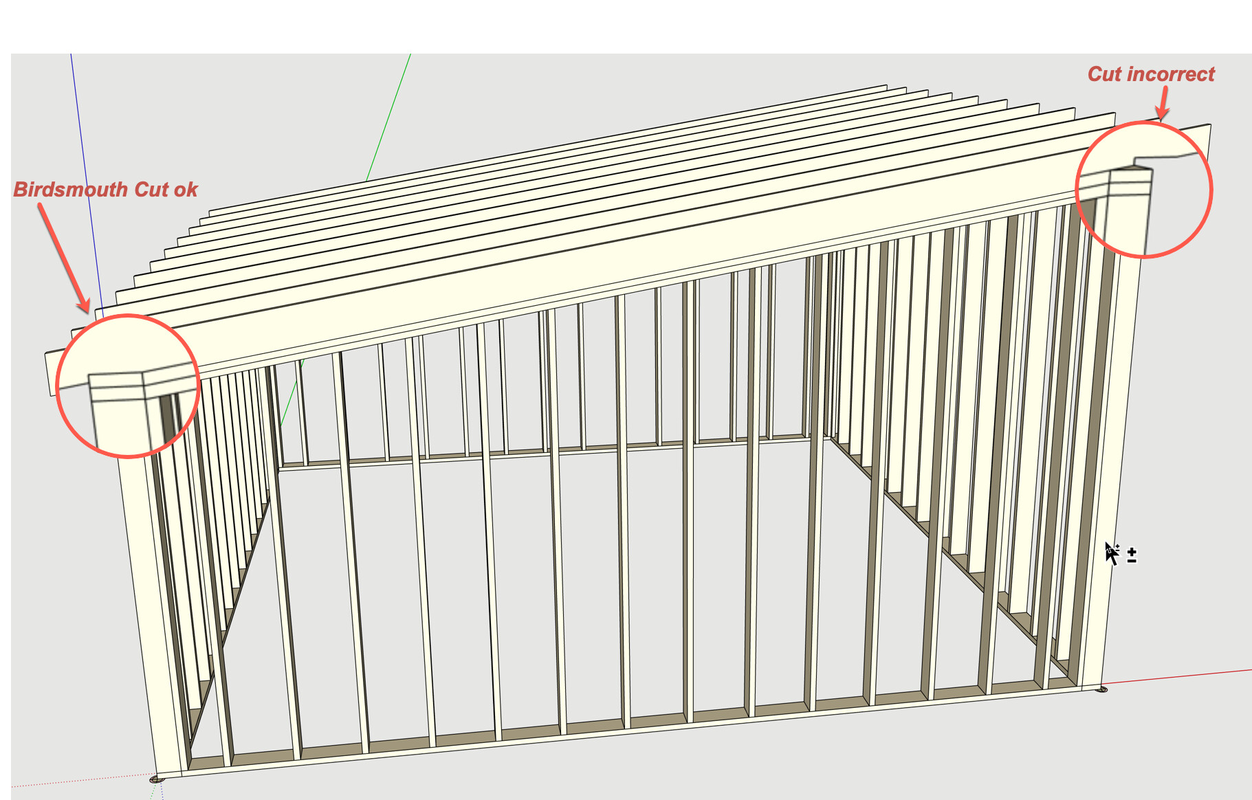
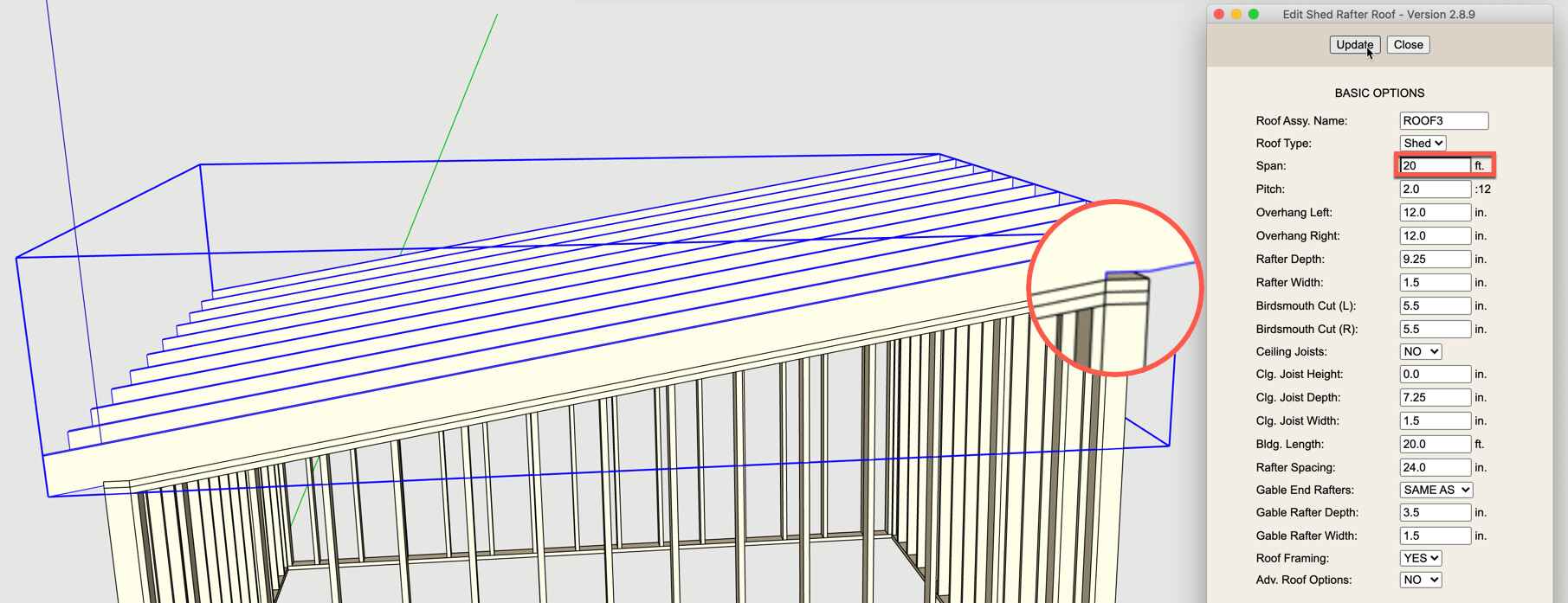
I need help in using the Truss extension to add rafters to a shed wall. Sheds are common in my project mix. This example is a 20’ square, with a 2:12 pitch (Image 1 & 2). The first problem is the front birdsmouth cut is incorrectly placed (Image 3). I can correct this by manually editing the span to 20’ (Image 4). Next, while the rear birdsmouth cut is correct, the front cut is not configured correctly (Image 5 & 5a). In this case, I am not sure the front birdsmouth is required. If I remove the front birdsmouth cut entirely, by editing to 0.01 (0 is not allowed), I can add a wedge shaped 3rd top plate (Image 6). The wedge can be added to the front wall assembly using the “custom” keyword or left as a native group. On the jobsite, I am not sure how a framing crew would solve this problem.
As you can see, a lot of manual editing is required to get a usable rafter assembly using the Truss extension. The addition of non-extension geometry (wedge) is a band-aid measure. A non-extension alternative would be to manually create the rafters. To preserve extension geometry compatibility and enable easy future editing I would prefer to use the Truss extension.
Maybe I am using the extension incorrectly or this rafter assembly is not possible with the extension presently. As always any suggestions or guidance is appreciated.
I’ve gone over this before, you want to lay out the shed rafter roof on the horizontal projection of the roof. I will need to adjust the code so that even if you select a non-horizontal projection it will force it into one.
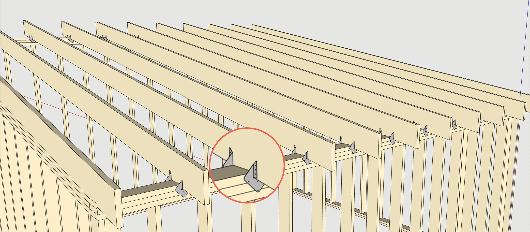
The birdcut at the higher wall is correct, the higher wall needs to project further upward to allow for a solid (flat) bearing for the rafter.
My bad ! You most certainly did, now TWICE ! Unfortunately, lost my local notes, and my mind !
I know how frustrating it can be solving a problem multiple times for the same customer. Thanks for your patience and these great extensions.
That’s why forum posts such as this are so valuable. I always search before I post. Hope this post will help me (when I forget again in a week!) and others as we seek solutions.
This will greatly help 3D challenged individuals like myself. Using a horizontal plane in this case seems counter intuitive to me.
Some screenshots to drive home this important work flow …
With every new model created, I strive for a cleaner, leaner and better organized model. In this example, the leaner aspect (lower poly count) will be discussed.
In framing models, I utilize Simpson Strong Tie connectors exclusively (@medeek also likes). Simpson provides a number of connectors (SU format) in the 3DW. These can be downloaded directly into the SU model. For example:
These are high poly, detailed and very nice looking. But as noted there is a cost (polygons and file size). Simpson also provides various, other formats (eg. dwg,dxf,pdf,rfa,ifc,sat) on their website. This details the formats for the H1 example:
The IFC format is a low poly representation which can be imported directly into a SU model. There is a substantial difference in the poly/size of IFC (Left) vs. SU (Right) files. File size decrease of 56%, edges decreased by 84%, faces decreased by 80%. Now multiply this by the number of models (think components) in the overall model. Now you know why models get sluggish over time.
The IFC models can be used as “place holders”. This will translate into better SU model performance (faster scrolling, editing, etc.). Bottom line, a significant time savings. And don’t fret, you can still use the high poly models for vignettes that will impress your clients. Be on the lookout for other manufacturers who may provide the IFC format, a winning alternative.