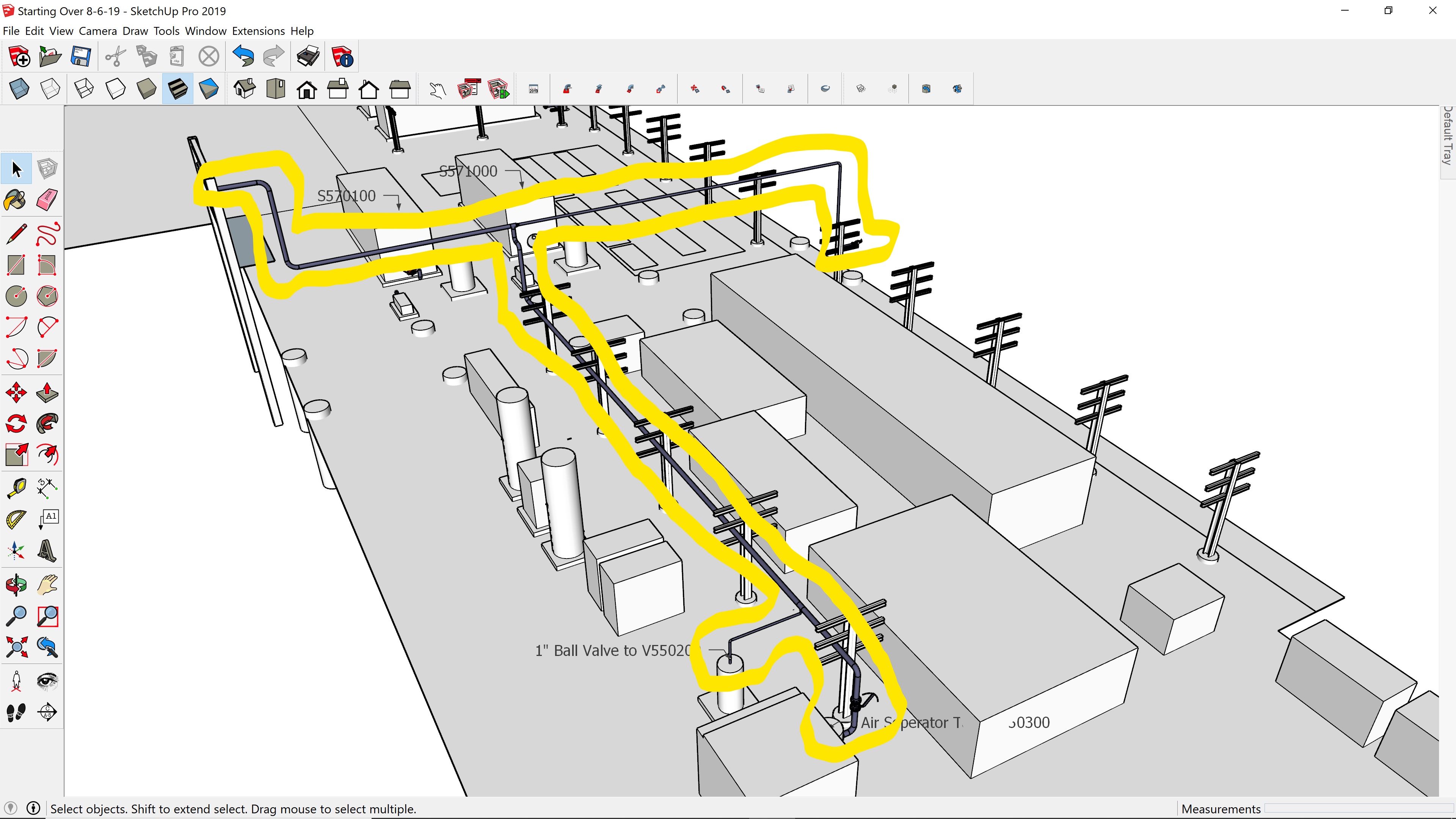
I am in some major need of assistance concerning this topic. I have attached one highlighted pipe run from my drawing and an example of an ISO drawing needed for construction. I’m trying to get it so I can take each separate group of pipe runs that I have and create an ISO drawing for each pipe run for the purpose of construction. How do I do this? Is it possible with Sketchup? The Piping extension I’m using is 3Skeng.
When extruding geometry with the native Follow Me tool, it leaves behind the path geometry.
A copy of the path geometry could easily become the skeleton of the ISO drawings.
Thanks for the reply Geo. 3Skeng does as part of its design leave behind a center path. 3Skeng then uses this to allow one to continue connecting fittings, valves etc as your doing your 3D pipe drawing.
Hi. Are you using SketchUp Make (free version) or one of the Pro packages that ships with Layout? Layout is SketchUp’s version of AutoCAD’s “Paper Space” which assists in creating documentation of all kinds. There is some setup required in SketchUp before moving across to Layout. Without Layout, then you will need some help (probably plugins) to get decent ISO outputs that are to scale. Let us know.
SketchUp produces excelent iso views to scale with its native tools. You just need to select ‘Parallel Projection’ first before selecting the ‘Iso’ button. Otherwise (if you did select ‘Iso’ first) just hit ‘Iso’ again after being in ‘Parallel Projection’.
(So selecting ‘Iso’ view is always the last selection of the two. Nothing more to it)
A forum members License, Version, OS & GPU are available in his or her profile.
As in the OP’s example below, piping isometrics are dimensioned schematic line drawings.
As a matter of practicality, piping iso drawings are not drawn to scale.


