I thought it might be helpful to try to summarise what I learned in order to get started with creating a Live Component. Some of the issues I faced are already documented in a previous thread Issues getting started with Trimble Creator.
@slbaumgartner suggested it might be helpful to create a downloadable document from this thread, and I’ve now done that. Here’s a link to it:
Live component tutorial.pdf (745.8 KB)
The images in the PDF are links to the images in this forum, so will only work if you have an internet connection while viewing the PDF (and otherwise, the document would be very bulky).
Here are some of the things I found I needed to learn.
1 General principles of using Creator
Creator works by creating a ‘graph’ of nodes, each of which performs a specific function or creates geometry, and has inputs and outputs. The output of one node generally connects to the input of one or more other nodes to affect its behaviour, unless it is the last node in a sequence that creates geometry.
Click on the ‘scholar’s cap’ to open a series of very basic tutorials about how Creator looks and works. That’s helpful, but didn’t take me very far. To get further, you needed to try to create something simple.
Start by creating a new node by double clicking in the Graph part of the Creator web page.
There’s a wide range of types of nodes, of which the most immediately useful to start with are value nodes and geometry nodes. You can see the options by clicking on the three-line menu at the right of the node creation box that pops up when you double click on a blank part of the Graph area.

A value node can be a parameter or a list.
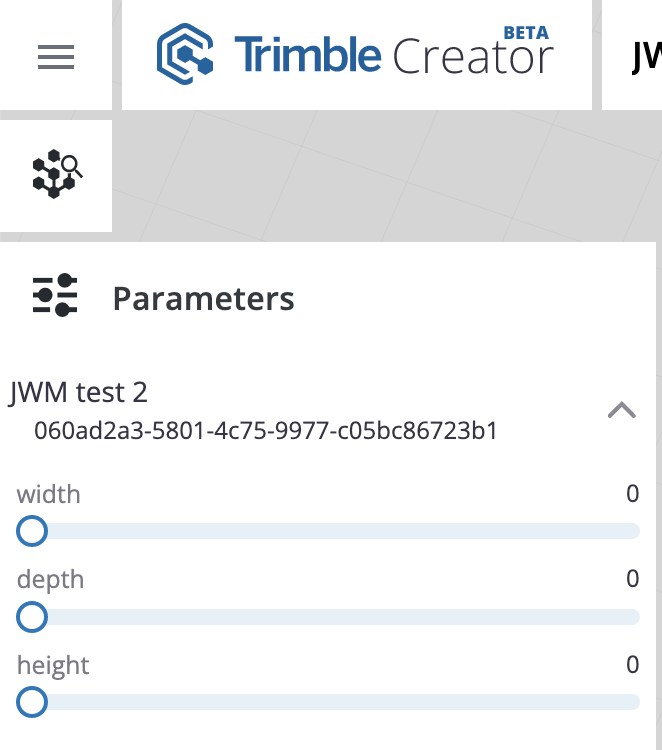
A Parameter will appear in the dialogue of inputs which control the Live Component. In Creator they appear if you click on the Parameter icon, second from bottom on top left of the Creator window.

The built in tutorial explains that you can convert a value node into a parameter most easily by selecting it with a left mouse click, and tapping the letter p on the keyboard. That turns the node from grey to blue (or vice versa if you tap it again). In the next image I’ve converted the width node into a parameter.

Or you can R-click and toggle the Parameter option with a L-click.

When I do all three, they all show up in the Parameter list:
By default, Creator works in length units of mm, and other units are for the moment bugged (but a fix is promised) - something that caused me initial grief when I had set the units to inches. (To set the units R-click on a blank area of the Graph window.)
You can adjust their values either by moving the corresponding slider, or by typing over the values on the right. And you can refine the behaviour by setting some of the inputs to the number node, for example to adjust the slider value in steps rather than continuously, or to set hard or soft max and min constraints on the input value.
Value nodes can have many different types:
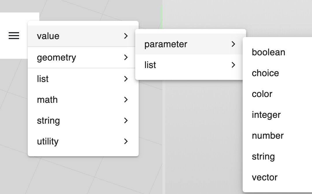
And geometry nodes come in several flavours too. I just used the geometry/create/box to start with. Or you can search for ‘box’ in the text box that pops up in the Create node dialogue.

I found it easiest to get started by thinking about what parameters I would want to control my Live Component.
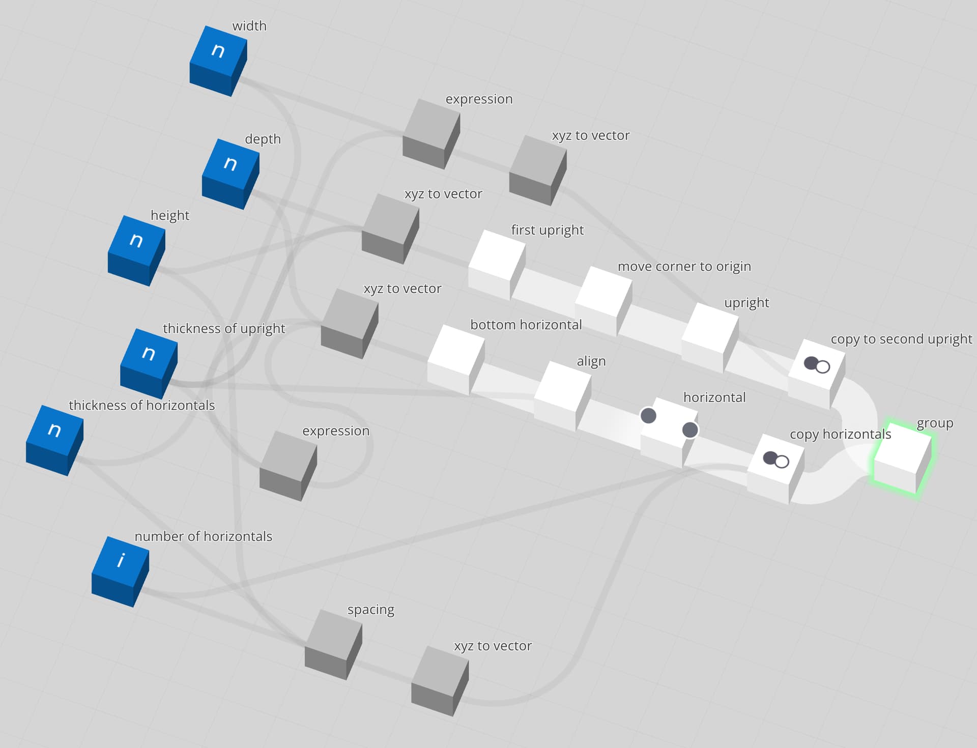
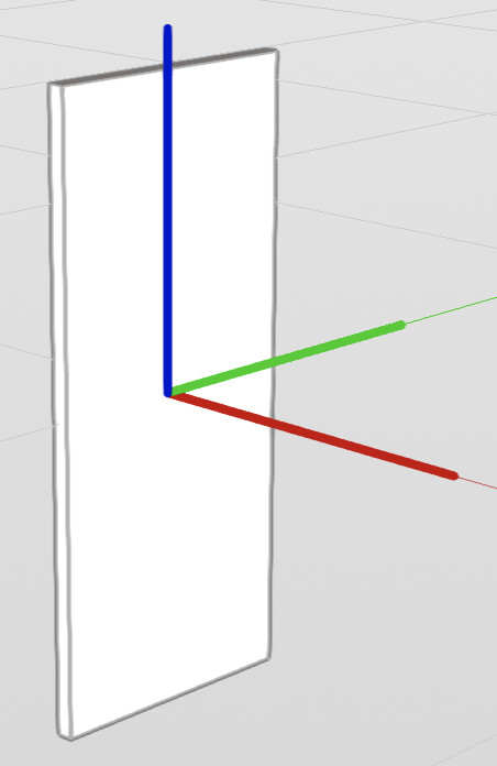
My initial aim was to create a simple ‘bookshelf’ - a construction with two upright sides, a top and bottom, and a space below the bottom shelf.
It would look like this in its simplest form when drawn.
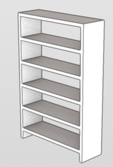
To create it, I would need a way of specifying its overall width, depth and height, the number of shelves, the thickness of uprights, and the thickness of horizontals, and the size of the space under the bottom shelf (the ‘plinth’ height).
There are quite a number of different ways to create geometry. I chose a very simple one: use ‘box’ nodes to create uprights and horizontals. There are several others which I only learned about later.
2. Create a box with parameters for width, depth and height
So I started by attempting to draw a very simple ‘box’ for one upright. That would need either three separate Value inputs for width, depth and height (x, y, z) dimensions, or one Vector input with three elements.
And I would need a ‘box’ node to create a rectangular geometric object.
So I started with three value nodes, attempting to connect them to the inputs of a box node.
You can give the values each a name, by clicking on the pencil icon beside the default name of the type of node. It only appears if you zoom close enough.

So I labelled my three number boxes as width, depth and height. You can still see the type of node by zooming in close again.


But I found they wouldn’t connect directly.
The box node expects these inputs (you get to see them by clicking on the left hand ‘dot’ on the node which appears when you hover the mouse over the node):

There are lots of sorts of value nodes, but I just want a number node (a floating point value).
A number node only outputs these items:

I didn’t (and still don’t) quite understand the purpose of the second output from the Number node (input is null) but the first one is straightforward - the value entered in the input.
You make connections between nodes by using the mouse to drag an output of one node over another node, and selecting which input to connect it to. (Or the reverse - connect an input of one node to the output of another).
But a value output won’t connect to the scale input of a box, which expects three values as a vector.
I find by poking around a bit that there is a type of node which takes three inputs x, y and z and outputs a vector. To make the connection between three values and the vector that the box input requires, I used an xyz to vector node, and connected it between the three value boxes and the scale input of the box node.
To start making the connection, click on the output dot on a number node, click on the value item, then drag the mouse to the xyz to vector node. That opens a list of x, y and z inputs. Click the mouse on the respective dimension to complete the connection between width value and x scale.

Make all three connections, and assign values to the parameters.
And connect the vector output of the xyz to vector to the scale input of the box.

Click on the box node, and the box itself will appear in the model part of the Creator window.
A point I kept overlooking is that by default, the box node is set with a uniform scale value of 1000.
That means that instead of my upright being 25 x 400 x 900mm it’s actually that size in metres, not mm - 1000 times too big.
Apparently that’s by design, to draw by default a box which is a one metre cube.
I kept falling into this trap, even when I had been told about it. I’m not at all sure that it’s a good idea. I expect that a 1 unit box should be drawn as a 1 unit cube, in whatever units have been set. And when I later tried to align the axes and position of my upright, I couldn’t understand why it wouldn’t move - because my movements were in mm, but the box was a thousand times bigger (in metres), and the movement was imperceptible.
To correct this, just type 1 into the uniform scale field in the box node.
That makes the box shrink to the size of a dot until you zoom the view using the spanner/wrench icon toolbar to expand the view (equivalent to Zoom Extents in SketchUp).

3 Position the box
I wanted my initial shelf upright to have its origin at its bottom left hand corner, like a default group or component in SU, so guessed that the way to do this is by using an align node.
That takes a geometry node as input, and outputs geometry at a different location.
When you first inspect the potential inputs, you see this:

But if you change the x align target from none to min, and also change the new field that opens from first connection or primitive to value, do the same for the y and z inputs, and also change the new last box to include in align you get this:

The aligned box now has its origin at bottom left (the min value of its x, y, and z coordinates), and has moved right, back and up relative to the original, to place it at the origin.

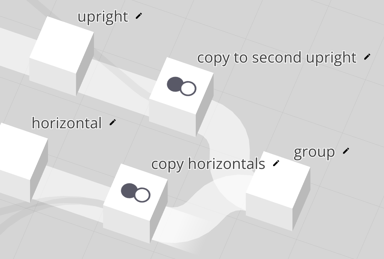
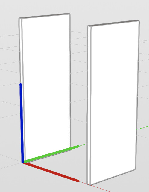
4 Copy the upright to the other side of the shelves
This involves using another type of node - copy and calculating the distance to move it - the width of the shelves less the thickness of the upright.
But at this point, I’ve used the width parameter to set the width of the box, not the overall width of the shelves.
We need another input - the width (thickness) of the upright to replace the original width parameter.
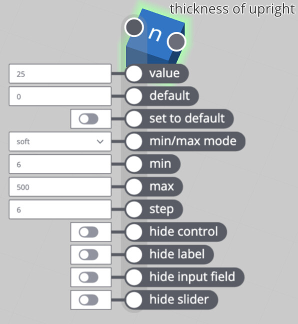
So add another number parameter - thickness of upright.
And while we are at it, edit some of the other values - for min and max values, and the step (the amount by which the parameter sliders move when you move the slider a small distance).
You can make these ‘soft’ or ‘hard’ constraints. The soft constraint sets the minimum and maximum values shown on the slider, but you can type a value outside this range. A ‘hard’ constraint won’t accept typed values outside the min-max range.
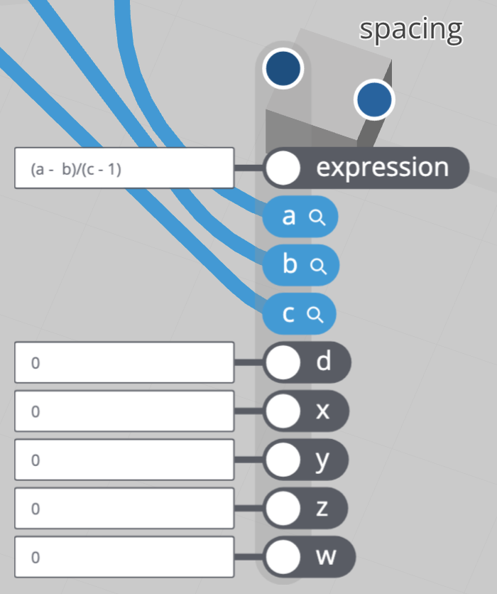
Now to copy the upright to the right, by a distance which is the overall width minus the upright thickness.
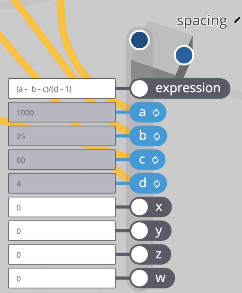
There’s probably more ways than one to do this. I used two more nodes - an expression node to calculate the x value of the move distance vector = width - thickness of upright followed by an xyz to vector node to create a vector [x 0 0] to plug into the translate input of the copy node.
Connect the width value to the input a of the expression node, and the thickness of upright value to the b input, and set the expression field to (a - b). For a simple expression like this, you can omit the parentheses.
Then connect the output result of the expression to the x input of the xyz to vector node, and the output of that node to the translate input of the copy node.
I set this up, highlighted the copy node, and nothing showed.
Ah, two further traps. First, I forgot to change the value of width to the overall width of the shelf unit, and had left it at the same value as the thickness of the upright. Result, zero - the copy just sits on top of the original. Second, unlike SketchUp, with which I’m familiar, the number of copies created includes the original, and I’d left this value at the default of 1 copy. Change that to 2, and a second upright appears when you select both the align and copy nodes in the graph.
That’s as much as I have time for at the moment.
To be continued in further sections as time allows:
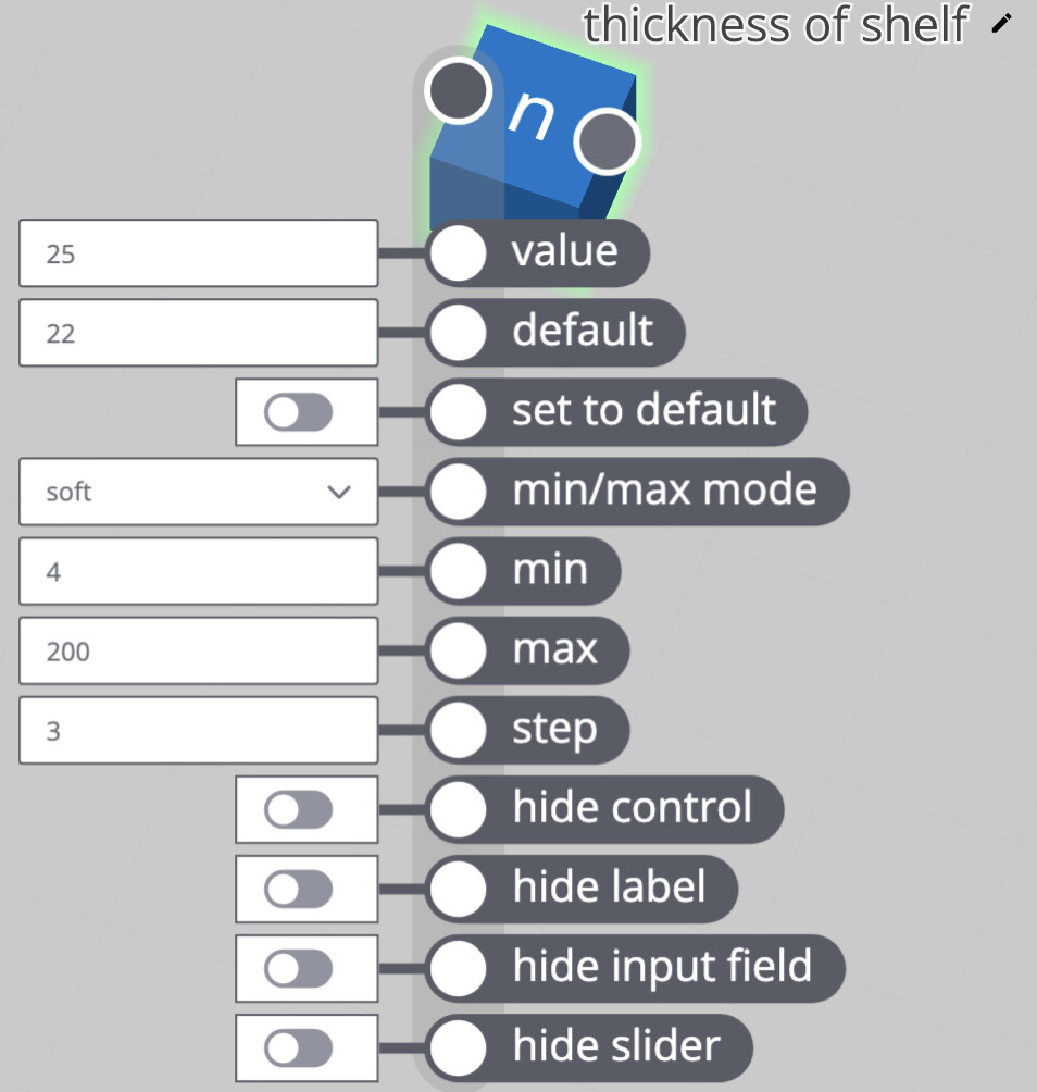
- adding a shelf and a new parameter for thickness of shelf
- adding a new input for number of shelves and making copies of them
- adding a new input for plinth height, and recalculating shelf positions
- adding an option and parameter to inset the middle shelves from the front of the uprights, top and bottom.
Edit - now done. See below.