I am trying to build a 3D model for a ball chain sprocket. After much effort in trying to build one model of the whole thing, I have realized the model has to be broken down into three different assemblies modelled separately and eventually “merged” into a single larger model. This will work, right?
The first item I am making is the base. I have created a 2D cross section of the base and then used the Follow-me tool along with a path defined by a circle to extrude the cross section into a round object. The circle was not joined to the 2D cross section. All seemed to go well, but I got an error message indicating the extrusion did not start or end on the path and that unusual results may occur. After doing the extrusion, all looked well, in spite of the message. I assume this is a “just in case” message that can be ignored in this scenario.
Once I produced the extrusion of the base, I made the whole assembly into a group and then ran the solid inspector. I ran into a couple of errors. I got a “border hole” error indicating that a hole in the geometry shares at least one of its edges with a surface. The hole in question actually shares its edges with two surfaces. The fix states to “draw over the highlighted edges to fix the border holes”. Do I just use the pencil tool to trace the edge of each of the circles (they are 48 segments in the circle that defined the path)? Not sure what that would do because I do not see any breaks in the offending circle and the surfaces seem intact. Anything else that has to be done?
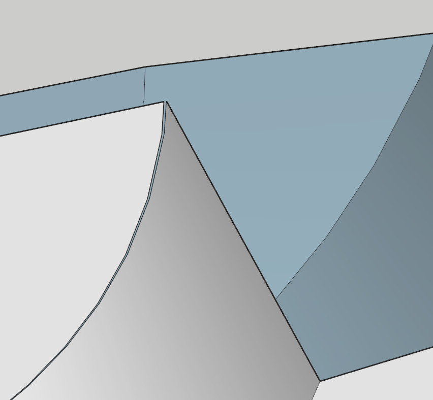
The second error occurs at an internal 90 degree angle where two surfaces meet. When you scroll in, the edges are highlighted in red and are separately by a tiny amount. They do not touch. Not sure why I would get this gap. The 2d cross section has the two lines meeting at their end points, so am not sure what is happening and how to correct it.
Once I get through this part of the model, I will create the other two assemblies, running the solid inspector separately on each of them, “merge” them, and then run the solid inspector one more time on the combined model. Will this approach work?
Any help appreciated, thanks.
Doug
This isn’t unusual when you have tiny faces. Working at a larger scale will help you avoid that. Either use “The Dave Method” or just model at a larger scale.
Here is the model of the base that has the border hole issue. It was downloaded from the web (really can’t tell what version of sketchup is on the web, but it was downloaded in sketchup 2020 format). Would like to try your scale up method, but am not sure how it will actually work.
Thanks,
Doug sprocket model 11 ball.skp (202.1 KB)
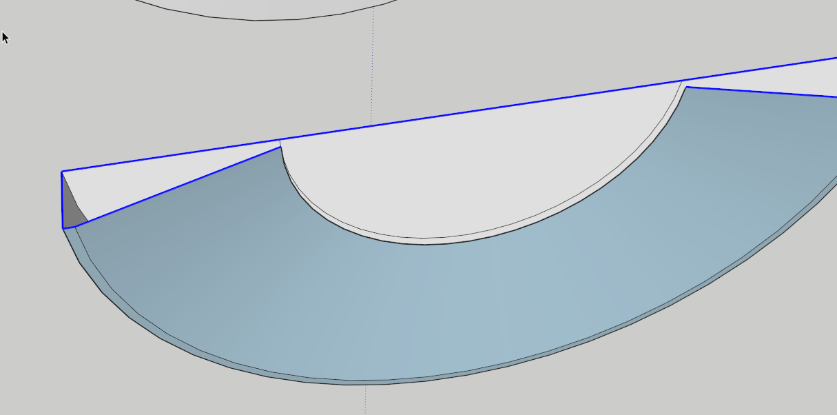
It’s 0.0034 in. long which is less than the minimum required to create the face. If you would erase that little line segment and it’s neighbor and replace it with a single edge, Follow Me would work as expected and you should end up with a solid group/component.
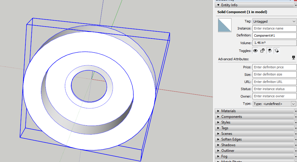
I did exactly that and made a solid component with no problem.
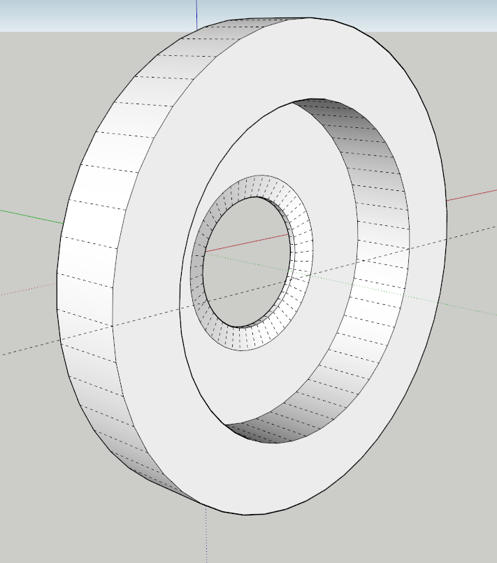
FWIW, you should get in the habit of dragging out the radii for circles on axis. In your model it appears you are dragging out at some random angle. The horizontal guideline in the next image runs across the center of your wheel. You can see that it doesn’t cross at a vertex on the edge of the circle.
Here’s my version and you can see that the guideline meets the vertices on the edges of the circles. This practice will make it easier to align objects to each other so they fit properly.
It works quite well when you are working with tiny details. It requires using components, not a groups. Below I have the profile and path wrapped up in a component, made a copy, scaled the copy up by 1000x (you might not need to go that big but I find it easier to do the math) opened the giant instance for editing, ran Follow Me, deleted the path circle and corrected the face orientation. Then I exited edit mode and delete the giant copy. Zoom Extensts returns us to the original instance of the component showing the completed part. TBH, in your model as it is at this point, at least after fixing the deal with the short edge, scaling up isn’t required but it might be later when you want to add more detail to it.
Thanks very much for what you have done here. I am having difficulty seeing that short edge in my cross section. I zoom in and I simply can’t see it. Given that the cross section is completed enclosed (given the blue colour of surface within the cross section), not sure why a short edge does what it does.
I have made the second and third assemblies of the model and still run into difficulties with these border holes and edges. Neither of them passed the solid inspection. One of them (which is extruded) seems to lose an entire face and once extruded has faces with dark blue, as opposed to white. Not sure why that is. Another issue I ran into was trying to align the three assemblies on the center hole. I assembled them, but I am not sure if the surfaces of the assemblies are in contact with each other or not.
Thanks for the tip on creating circles on an axis. When I tried to make my first model, the edges of the circles were always “misaligned”.
I have attached the same file, with the added assemblies. It remains a work in progress.
Thanks for your help. Much appreciated.
Doug
Edit the style and turn on Endpoints. That’ll make it easier to pick out the short line segment.
Every edge is treated separately. I guess I don’t know why you would divide the long straight edge segment into multiple segments.
You still haven’t fixed the problem with the extremely short edge segment so it shouldn’t be any surprise you are still having the same problem.
The piece with the reversed faces has the same basic problem. There’s no surface where there should be one and I’m guessing there shouldn’t be one where it looks like there should be a central hole. (It also need to have its face orientation corrected.
In both this piece and the larger one you could avoid the problem with the tiny face using “The Dave Method” as I indicated before. You’re still using groups, though.
Do you have a link to any technical info about the sprocket you are trying to model?
Well, this is a work in progress and am still experimenting. There is no technical info on the sprocket. I am using a sprocket (12 hole) I made out of wood as my starting point and template for this eleven sprocket (I used Sketchup to produce a 2D drilling template for the 12 hole sprocket. It worked, but just barely - hence the idea to make a 3D Sketchup model). The sprocket is used on a wood lathe in a jig to cut spiral grooves in wood with a router as the wood piece is uniformly rotated while the router is moved along the length of the piece. With different diameter sprockets, one can alter the pitch of the groove being cut. The 11 hole sprocket will likely be the smallest sprocket I can make because of other limitations. I will make larger sprockets that I can interchange to alter the pitch (may be up to 50 - 60 holes).
My aim with the 11 hole sprocket is to produce a 3d model that I can have made up on a 3D printer and try it out. I can’t make it out of wood because it is difficult to index the piece equally 11 times to produce the holes that make up the sprocket and the spacing is getting too small for wood remain structurally stable. If it works for 11 holes, then it can be scaled up to any larger size sprocket within the limitations of the lathe.
I did not have a chance to correct the first assembly when I sent the file. I will go back and try it again and see where I went wrong.
Much appreciate your time in helping me out. Lots of power in Sketchup, but it has a bit of a steep learning curve and I find the web version has a lot of idosyncancies that make it a bit frustrating at times. Most of the tutorials focus do not focus on the web version, so simply finding where the tools are can be a bit time consuming for the most simple of operations. I will get there, though. Again, thanks for your help.
Doug
Might be worth spending some time with simpler projects to get used to the user interface. Other than that, the modeling operations are the same.
I hunted up some dimensions for bead chain sprockets from a company called Raymore Tool. The didn’t list a sprocket for 11 so I did 12. I started by setting Units to Meters instead of inches to avoid the tiny faces issue. The dimensions on the website are given in inches. The 12 pitch sprocket for 0.25" bead chain is 1.090 in. dia. so I modeled it to be 1.090 meters in dia. If you are modeling to them make it out of wood, the conversion later is easy. If you are going to 3D print you can either export as is or you can scale it down. We’ve talked about this before, I think. If your slicer gives you the option to set import units, you shouldn’t need to scale down.
OK, profile of the sprocket without the holes for the beads and a circle for the path. The circle is drawn out on axis and I used a multiple of 12 for the number of sides on the circle since there will be 12 bead holes. You want to have a pitch of 11 so use a multiple of 11 for the number of sides. I have already modeled the bead and made a total of 12 bead components. Note that I am working about the model origin so I have a good fixed frame of reference.
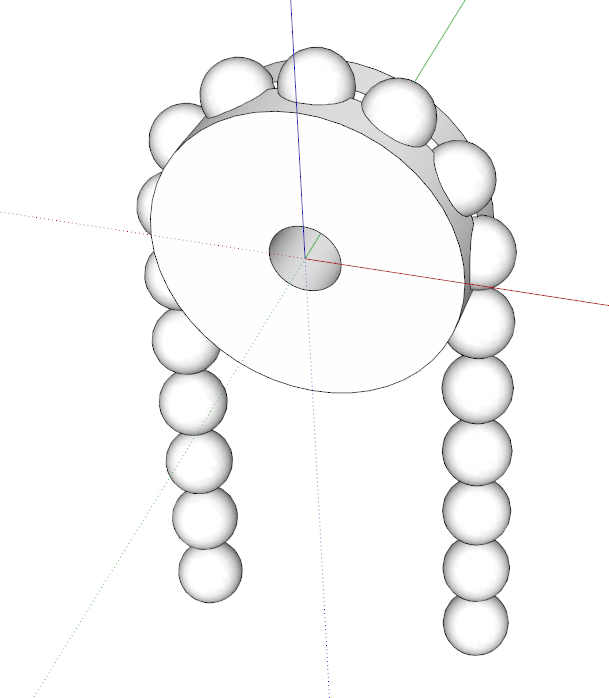
Here I have a set of the beads in place around the sprocket. the beads and the sprocket are each solid components. Since I am using the Pro desktop version and have access to it, I used Subtract from the Difference Tool in Bool Tools 2. In the Shop web version you would use Subtract from the Solid Tools. It’s not my favorite because it will convert the component to a group and I prefer to keep the objects in my models as components. As I wrote before this is important especially with the Dave Method but I don’t use groups at all in my modeling.
Wow!! I am still struggling with my various groups and you have produced the entire thing from scratch. I have something to aim for! I have re-done my 2D cross section of the first piece and found that nuisance edge piece hiding there. I will have a go at your Dave method tomorrow because I still get faces not extruding, particularly on the last piece that you highlighted. Have done it three times and the inner most face is not generated.
You certainly have the idea for the sprocket. I will check out Raymore tool. My pitch circle was 1.1" for 11 holes. Your pitch circle is 1.09" for 12. I have no specs on my ball chain that I am using. It uses 1/4" balls and I have estimated the distance between centers of the individual balls as best I can to determine the pitch circle, but maybe the Raymore tool site has some additional info I can use.
I am retiring for the night.
Thanks again.
Doug
I tired to use the scale method to eliminate short edges on one of the assemblies, to no avail. I scaled it twice, once at 10x, and then again at 100x. Although in each case I could produce a solid shape with no missing faces, I ran the solid inspector in each case on the scaled up assembly and in both cases, ended up with the same number of “short edges” (288) in the solid model as I did without scaling, so I am back where I started (I think).
Interestingly enough, I have also a 2017 basic version of sketchup. I created one of the assemblies using that program and it produced the solid model without any scaling or other issue. I couldn’t run the solid inspector because it was not available in that version, but the model came out without any hiccups, unlike what I have experienced in the web-based version of sketch up shop.
Thanks for all the feedback and assistance. Am learning quite a bit here with this modeling exercise and looks like I still need to learn quite a bit more!
Doug
If the thing reported as solid, the short edges shouldn’t matter. I wonder why you still haven’t done as I described–scaling up by 1000x and getting rid of the short edge. Did you try redrawing the profile?
It is available as an extension and will work in SU2017 Make.
“Scaled up assembly” Do you mean that you are checking the old groups to see if they received changes made to your new components created from the original profiles? You need to “rebuild” the assembly from the new components. Do you mean that the individual parts are solid and now you are trying to combine them and having a problem?
*edit: as a btw, Solid Inspector is a time-saver but not necessarily a great education device. Showing you what’s wrong prevents you from figuring it out on your own, as well as from forcing you to adopt best practices to prevent issues from arising in the first place. For experts it’s a useful tool but for learners it can be, at best, a net neutral.
I found the short edge that was creating the original problem and deleted it. I have also redrawn the profile and extruded it. I tried scaling 10x and 100x and extruded at these scale ups. At those scales, I was still getting “short edges” identified by the solid inspector tool. I never tried 1000x - I thought 10x and 100x would be sufficient to clear these errors, if they are even errors. I have also redrawn the profile of the second assembly and did the same scale up procedure as I did on the first, with the same results.
I have started over with a new file. I have redrawn the cross sections of the first and second assemblies and extruded them. The shapes look better. I have not yet tried the scale up exercise but will do so at 1000x. Thanks for getting back to me.
Any degree of correction-recreation from the profiles to new components is not going to update the “assembled” groups in your second upload. Just take your successful solid components and “rebuild” the assembly with them (or, in a hypothetical future workflow, go straight to printing them).
Working at 1000x is harmless but a bit overkill. Even 10x resolves the offending .0172" edge on “disc two.”
Correct. With the profile fixed to eliminate the very short edge, it doesn’t need to be scaled up at all.
As I wrote yesterday, I use a scale factor of 1000x because I can work directly in meters as if they are millimeters. When I work in inches, I treat 1 meter as 1 inch. It’s an easy conversion either way.
When it comes time to cut the sockets for the beads, you may need to scale up that far because there’s another place where tiny faces might be created.
Ok, thanks for all the responses and great advice. I want to make sure I understand the advice provided.
Clarifications - the 0.0172" edge highlighted in a picture above by brianmowrey - is that edge simply too small for sketchup to deal with at a 1:1 scale? Scaling up, in conjunction with the use of sketchup components rectifies this?
In Brian’s reply, you state that at " even 10x resolves the offending .0172" edge on disk two". By “resolves”, do you mean a surface is produced by that edge on the 10x version of the disk that remains as a surface when scaled back?
In my new file with newly drawn cross sections for the two disks (which I am calling assemblies), the extruded solid models both look fine, much better than my first attempt. All surfaces are present, without any scaling. All is good until I run that solid inspector on each of the two disks. Once I do that, it highlights each of the models as having “short edges” but provides little guidance as to what to do, apart from erasing and redrawing - that doesn’t seem to resolve anything. No other errors are identified. Can I simply proceed with the solid models as they are or is some scaling necessary? In my previous attempt, scaling created the all the surfaces, but I ended up with the same “short edge” errors with the solid inspector when exercised on the scaled up models, so not sure what I actually accomplished. I got the surfaces corrected, but didn’t clear any of the “short edge” errors. That is what I really don’t understand about the scaling processes described.
I will try scaling on my new file and assemblies to see what happens.
Thanks for the help and guidance. I truly appreciate it.
Sorry - I’m still unclear what you mean by “the solid models.” If you still aren’t using Dave’s component’s/scaling advice, I can’t lean in to any recommendation without having a better picture what your current f-m results look like and whether said results show as solid in Entity Info or you just mean that they look ok. Either way, this is why working in scaled up- land is preferred by lots of users
What I meant was the extruded shapes. They looked “solid” from a visual standpoint. However, I just did a check on the Entity info for each of these assemblies and Sketchup Shop indicates they are both “Solid Groups”, so is that sufficient (in spite of what the Solid Inspector states regarding “short edges”) to consider these assemblies as being “solid” for 3d printing?
Regarding Dave’s scaling advice, what is puzzling to me is that when I scale up an assembly and run “Solid Inspector” in Sketchup Shop, I get the exact same number of “short edge” errors as I do on the unscaled assembly. I simply don’t know what to do at that point to eliminate these errors, if they are even errors. Your previous comment on the use of Solid Inspector as an education tool is “net neutral” rings true. As a newbie with this tool, I really don’t know how to interpret what it is trying to tell me regarding “short edges”.
As an aside, I created the same assemblies in Sketchup 2017, no scaling - I created the cross sections and extruded them with the followme tool. Both came out as “Solid Groups” in the “Entity Info” dialogue box. I also used the extension “Solid Inspector 2” in Sketchup 2017 to see if I got any errors. “Solid Inspector 2” assessed both assemblies as clear (“shiny”, actually). I could not use the Extension “Solid Inspector” because it simply froze the application - not sure why.
So, from what I understand, both of my assemblies created in Sketchup Shop can now be considered “solid models”. I will work on my third assembly, the sprocket mechanism itself and bring all three assemblies together.
Thanks.
Doug