Hello!
I am trying to resolve an issue I am having regarding “snapping” to a mid point.
I’ll try to keep it brief…
I have modeled several objects (Desk, Frames and such) and I am trying to align it to the center of my working space (A room I am designing).
Issue starts when I am trying to grab the middle point of that component/group and move it directly to the mid point of the room… at the beginning I tried finding the mid point by going directly to the floor/wall while locking the object to one of the axis.
Given that I have found it very difficult and very inaccurate (for some reason). I decided to draw a couple of lines on the “floor” (one vertical and one horizontal), making sure that these lines correspond with the dimensions of that room.
I am so baffled and confused as to why I am experiencing such deviation (it is in the mm, true… but it is still quite bizarre).
Measured and re-measured the components I have made but they are also at the “correct” size.
I am pretty certain that I am doing something wrong… it is just so frustrating to try and align everything over and over again, while the deviation still persists.
I am new to SketchUp, yet so far I have managed to make everything pretty accurate.
As @Wo3Dan described, you can use guidelines to define reference points to aid in positioning. You can also use inferencing. Grab the object by a point that has some destination. Also lock the inference direction. In the following I grabbed the desk at the midpoint of the back edge of the shellf, I locked the move direction to be parallel to the red axis using the right arrow key and move it to align with the midpoint on the back wall. Then I grabbed the desk by the corner of the bounding box and moved in the green direction back to the wall.
You could edit the desk component to add some temporary geometry to identify the center or whatever point you want but probably most of the time using the available inferencing will be enough.
Dear People!
Thank you for your responses!
It seems that i have explained myself quite terribly…
When using the inferencing or the guides I have still managed to get a slight deviation when trying to place the components at the middle of the floor.
I am beginning to think that the position of which i am holding the object might be the issue, despite the fact that based on the indicator, I am indeed holding the middle of it.
I will share a few examples:
in this example I am “catching” the mid point of the group (indicated by its purple dot - which also states midpoint of group etc…)
when measuring sideways it claims to sit exactly in the middle of the room!
However… in this example:
I took the bottom part of my panel (the base of that component) and drew a line in the middle of it (made sure several times that I am indeed in the center of the component - it is 70.1cm wide, so i have placed it exactly at the 35.05cm point - the cyan dot)
for the sake of making sure I am aligning it to the middle i entered the “floor” group and drew a small line (again - exactly at half the width 305cm/2=152.5cm) and look at that deviation!
I am genuinely clueless
Anyways, I hope someone could direct me towards my error (assuming I am doing something off).
If you snap to geometry in the component it is possible that there are multiple small lines making up the edge of a surface so it could be the middle of a segment that is broken, and if it is a small segment at one end of the line or the other you might not be properly in the center.
Likewise with using the grips to grab the middle of a component or group - you might have a hidden bit of geometry sticking out so the bounding box isn’t representative of the actual visible geometry.
Another trick:
Move the component or group at its midpoint to the edge of the floor in the room.
Move + Copy the component to the other edge making sure you are locked in the proper axis.
Once placing it at the other end press /2 and enter.
Select the component or group that should now be precisely 1/2 way between the first and second copy. Cut this component (Cntrl X)
Delete the remaining 2 components.
Edit>Paste in Place and the component you cut will reappear exactly where you cut it from.
I find this graphic way of doing things much faster than measuring / drawing guidelines / etc. especially if you have a shortcut created for ‘Paste in Place’
You wonderful people!
well it appears that the issue is indeed with lack of symmetry.
The culprit is actually a fractional rotation which accumulated to a measurable deviation.
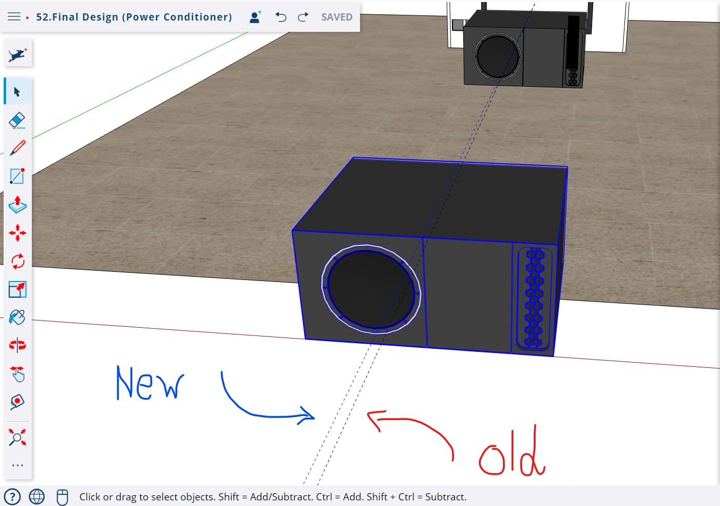
Noticed that when trying to to re-align a new Subwoofer I picked from the component menu and saw it won’t align to the same guide from within that component!
Anyways, thus far it seems to be it… i know it is a tad impractical and very time consuming but I’ll re-align these center based components to the Origin and then move them to their location.
Not sure if you can do it on the web version but often it helps if you edit a style so the edge (line) color as red, green, blue - this allows a quick visual guide to see if things are on axis or not. When I get a model from a client this is one of the first things I do as I begin to work with it.
@yotamlifshitz, ‘Color Edges by Axis’ is available in SketchUp Web Free. Search via 'Color …:
by Tag
Edges by Axis
Edges by Material
Edges all the Same
Good to check with ‘Color Edges by Axis’ but it certainly does not for 100% ensure you that colored edges (red, green or blue) are on axis. Within tolerance you’ll also get colored edges with errors in their endpoints. Drawing with this style helps a lot to avoid these errors. For it will be hard to fool SketchUp, thus to draw within the tolerance yet still not on axis.
There is something fundamentally wrong with the workspace of your model.
Not sure why you have the locked component at the origin but I suspect it is related to the problem.
But most importantly creating a rectangle from the origin should be flat, but with your model it is very slightly off axis. The axes are not available for reset so that is strange.
Copy and paste into a new workspace and a rectangle can be created flat.
I cannot explain why.
You also have some incorrect Tag usage, a tiny edge at a distance along the green axis and some hidden geometry to the left of the green axis.
@Wo3Dan thank you sir!
I will look into it and avoid counting on it as a foolproof system to elude axis related shenanigans
Dear @Box, I assume it could explain the vast irregularities I am experiencing in this project.
The locked component is my wrong doing… I have had many issues trying to reset the axis at the early stages of this project (please bear in mind I started using SketchUp 3 months ago haha).
So I tried to recreate an “Origin” point to re-snap back to.
In regards to the rectangle deviation you experience, well I am not tech savvy enough to know the reason… yet, I do have a suspicion.
When I first started a few months ago, my browser of choice was Opera.
when launching the website it kept telling me that I might experience some issue (apparently Opera is not yet supported).
Cannot determine whether or not this is the reason but… maybe it could…?
About the tags, well I do need to redo the entire plan… will address that as well.