I am utilizing the Dynamic Component capabilities of Sketchup Pro 2020 to create commercial cabinetry and fixtures. I have about 3 yrs experience with Pro and Layout. It has worked well and given me the needed resources to design and provide construction drawings for complex products.
I now have a need to include some clearance cutouts in cabinet side panels. My problem is when drawing the cabinets using dynamic components. When altering the size of the cabinet, the sde panels change height and depth. Currently the cutout size is altered along with the panel.
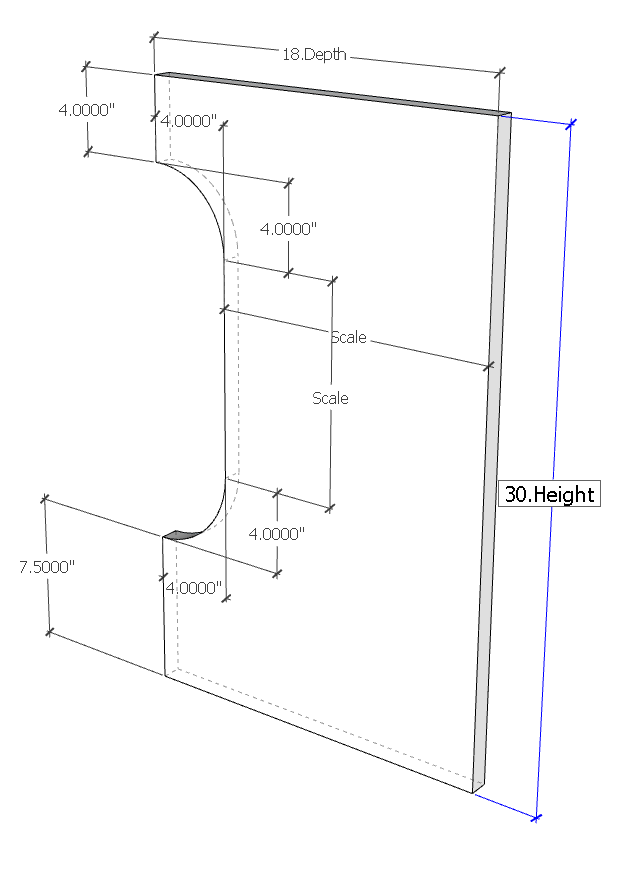
The height of the cutout can be scaled with the side panel. However the 4 inc radius and it’s location relative to the top (4 inches) and the bottom (7.5 inches) needs to stay at those dimensions.
In the Component Options window the user can input a height and/or depth dimension within a specific range that allows space fo the cutout.
Split it into subcomponents. Some of them fixed size and some of them resizable. Hide the edges where they meet to make it look like one component. Sometimes you’ll see a white line where they meet, depending on your style settings, but it’s not that noticable.
however the five parts should be the larger area, each arc and then their adjacent areas below or above, otherwise the arcs will no longer be quarters. Its a good idea to keep parts as solids with faces, lines hidden, then can use outershell if you wish to send the panel for cutting
I think it could be done with 4 subcomponents. The Top Arc and Bottom Arc as in my file. One large resizable panel with hidden edges next to the top&bottom arcs. Then a 4th component which is just the face between the two arcs with visible edges.
I change my mine again, given the brief, so Gordon your first solution is correct, however if you wish to move or change the size of the arcs then consider separate parts for them and the area above or below them,
Thanks for the assistance. I have chosen the main panel an two extensions with the arc cutaways. I placed a partial surface on the edge of the main panel where it meets the extensions. That approach is an acceptable balance between appearance and complexity.
I also use Fusion 360. It has constraints features which would work well in this type of design. I use F360 more for machinery design.
All in all, I find Sketchup to be quite a remarkable product.