I’m trying build a mounting bracket for a power supply. I have the base and one leg built. I figured the easiest way to get the second leg would be to copy the first, flip it and attach it to the base. First two steps no problems. Now I can’t get the leg to align with the base in more than 1 plane.
Image:
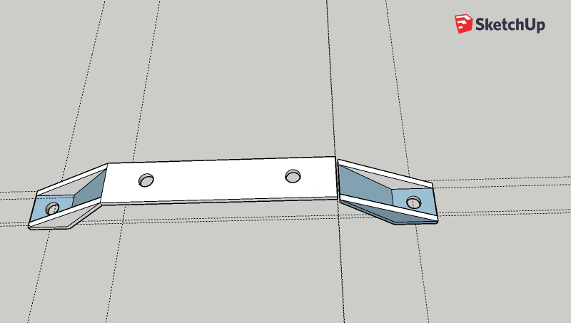
I was able to align these pieces, but any move like this would be easier if group your part, then flip it. This will give you a clean bounding box that will inference snap to the base (which you should probably also group)
Are you going to make the leg as multiple parts or as a single part?
If you are going to print it as a single piece, you will have a lot of cleanup to do after joining the end to the rest. A different approach would result in a lot less mess to clean up.
Here’s one way that yields a printable model with minimal cleaning.
Draw a rectangle and extrude it to make the side thickness. Many people start out trying to outline their parts on a 2D surface but that quickly results in more work than they need to do. I made the rectangle’s Y dimensions a little more than the overall Y dimension of the bracket but the length (X dimension) is the same as the finished part.
Then draw the angle for the inside edge of the bracket. I used a few guidelines to get the angle right. Then I used Rotate/Copy to rotate the angled line to the other end. Rotation was about the center of the part on the Y-axis. Connect the ends of the angled edges with another edge.
Use Offset to create parallel edges 2mm from the edges in the previous step. This defines the thickness. Add the diagonals for the butresses.
Use Push/Pull to get rid of the excess and to extrude the the bracket to half its final width.
Move/Copy to copy the half bracket. Flip along the blue direction to mirror it. You could also copy the geometry, use Scale with -1 to make the mirrored upper half and then Paste in place to paste in the original from the clipboard. I used Flip because it’s easier to show in a screen shot.
Move the upper half down to the lower half.
Erase the seam lines.
7, Add the holes and make it a group or component. It should be solid from the beginning and require no further cleaning.
I’m on my phone so I can’t look at your model. However, the keys to this sort of operation are to click a point that needs to align with a destination point and lock the direction of movement.