Visual Schedule for Doors and Windows

I am exploring the automated generation of visual schedule for doors and Windows from a house model.

The approach is described in this video.

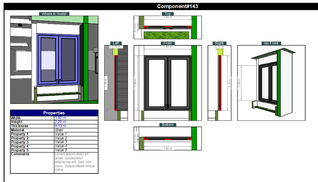
A visual schedule is a Layout document which includes various views of the doors and windows in their surrounding contexts, typically elevation and section views, floor plans showing where are the doors and windows, and a summary table of all windows and doors with some information on each one.

For instance, here is the visual schedule in PDF (from a Layout document) for the house taken from 3D Warehouse below:

AA - villa+050321 by MrMinh77Vlog__schedule_Wed-15-Jan-25 21-43-56.pdf (885.9 KB)

It took roughly 1 minute to generate the visual schedule.

The plugin (FredoSchedule) would include 2 parts:

  1. Configurator, where you identify doors and windows, their surrounding elements (typicaly walls, insulation, …) and a set of other properties (opening directions and type, make, cost, etc…).
  2. Generator, which creates a Layout document from this information, with a few options and parameters to specify the desired views and page organization.

The Generator extracts the doors, windows and their surrounding elements into a separate model (Schedule model) and creates all the scenes, tags, section planes which are needed to generate the Layout document.

This allows to leave the original model unchanged, and avoid that it is polluted with scenes and tags for the schedule.

The generator should have some parameterization to fit user’s needs.

  • You can select the views you want to go to the schedule
  • The layout document can be generated from a Custom template document, so you can include your own cartridge, choose the paper size, etc…
  • All section views and section boxes have cutfills painted with distinct pattern materials (hatching) depending on their physical material.
  • Properties included will be configurable
  • Dimensioning and annotation will be based on indicating the connection points in the Sketchup model.
  • You can also specifiy a detail view for some doors and windows (kind of zoom)

For the Configurator, the idea is that if the model is created with some specialized plugins like FlexTools, Medeek Suite, etc… or tagged with plugins like 5D+, IFC manager, …, then it is possible to get this information for the schedule generation and avoid to re-enter it manually.


At this stage, I am interested to know if there is any interest for this type of automation and if there are specific requirements.

Note that, because of the limitation of the Sketchup and Layout APIs, the generation of the visual schedule has to be FULLY automated from the model and the information given. This means that if there are any change, you need to regenerate the whole schedule document. But the time to generate it by FredoSchedule will always be shorter than doing it manually.


6 Likes

We would pay for this if it could be adapted to other types of schedules. We have a need to generate millwork element schedules like cabinets, cabinet door and drawer faces.

2 Likes

This is probably possible. I think the main evolution would be about showing dimensions.

Do you mind to send me a model and an example of schedule.

1 Like

I can this weekend. Thanks!

Some kind of flexible filtering of what to include in a schedule would be ideal. By tag, by name, by material, by…

1 Like

Yep this is basically what I was asking for.

Do you mean for selecting which door and windows go to the schedule?

Currently, this is rudimentary, but it can certainly be done with more criteria (tag, name, type, etc…)

Note that the plugin is not fully developped. I just validated the technical feasibility of the generation. The UI for the Configurator and a part of the Generator is still to be done, but UI is just work and time.

3 Likes

I was mostly thinking about the way I make my schedules in Archicad and Revit. There, whatever the thing I want catalogued, I try to set up filters that automatically catch, for instance, objects that I add to the model.

2 Likes

I can’t speak for Anssi, but what I meant was a table based on all objects of a certain tag. For example a tag called “cabinet doors” and it outputs a schedule of all cabinet door objects in the model.

1 Like

I think there is some confusion. The plugin does generate a visual schedule of doors and windows. Of course, you can have ways to select the elements, but that’s not the difficulty or purpose.

What I try to validate is whether it is realistic to automate the generation in Layout to a level which is functionally acceptable for architect documentation. This is versus doing it manually or creating many scenes, tags and section planes in the master design model to do so.

I am not an architect and thus I have no clue whether what is generated is too simplistic, or simply not suitable for professional documentation (planning, construction, permit, …).

3 Likes

This is really usefull @fredo. This is an example of a drawing we usssually attach in Spain for permits and construction documents. (I hope it helps you).
Instead of extracting each window view from the model I collect all of them in a SketchUp model from which I send to LayOut. When I’m modeling I use the components from my library that are Ifc classified so I can extract info to make my schedules.
carpinterias página 2.pdf (490.1 KB)

4 Likes

O thibk this is really useful @Fredo6

My windows and doors schedules are usually more complex than those of @rtches but the principles are the same.

I agree with the selection methods that have been suggested by @Anssi and would add Ifc Classifications to them. Usually name filter or tag filter will be enogh though.

If the schedules you produce for windows and doors can be confugured with more and less scenes and the user will be able to see those objects with more or less context, depending on some sort of user input, then the plugin could really be adapted to any object.

Typical scenes needed would be:

Windows - front view, vertical section, horizontal section, zoomed in details for vertical section and horizontal section. Ideally we should be able to draw on those details in order to add water proofing, sills, aluminum profiles, and so on.

Doors - elevation and horizontal section. Sometimes vertical section and details too.

Cabinets and Kitchen Cabinets or islands - elevation, iso view, vertical section. Some details on special cases.

I could go on and on with objects:

Stairs and escalators - Multiple horizontal and vertical sections

Elevators - elevations, plans and sections

Revolving doors - elevations, vertical and horizontal sections, some details.

Curtain Facades - elevations, horizontal and bertical sections, a lot of details…

Exterior Walls and Connections to slabs - detailed vertical sections, and maybe iso views, to create some sort of fake 3d details.

I design a lot of stone sinks and showers - plan elevation, section, iso view and sometimes exploded views of stone slabs.

I don’t know how far can this go but I maybe it could fit all these objects.

1 Like

Continuing the discussion from Visual Schedule for Doors and Windows:

Great idea
Yes very interested
We do a whole door/window schedule generally all together on one or two a3 pages.
We take say from archicad model the elevation
Show width/ height and configuration
Schedule below each elevation
Type
Size
Glass type
Area m2 (energy assessment)
Direction of opening
Remark/ note

1 Like

Window and Door Schedules are one of the biggest annoyances when working with SketchUp. I currently do them manually in excel, but having this automated, like other software, would be huge!

Typically, I have 3 schedules. Windows, Exterior Doors, and Interior Doors. Having these separate would be key.

Is nobody doing schedules for closets?

This is an excellent idea!

It would be fantastic if the level of documentation produced could be selected so that a simple drawing like the one ‘rtches’ shared could be produced, or the much more detailed original Fredo version.

Preset elevations, sections, and plan views generated and sent to layout based on a coordinate input (i.e. the location of the object being described, i.e. a door, window, whatever) would be a game changer for millwork/cabinetry stuff and we would definitely pay you for it.

Still on my list to do this weekend. I’m excited!

We would definitely use this. Automatic labeling of doors and windows would be helpful as well but more helpful would be 1)the generation of a table with all the units and dimensions 2)the visual schedule

I’m a joinery manufacturer who also designs new or renovations for houses and other buildings. The renovations are nearly all of historic buildings and the level of detail needed there can be quite high. (Where we live, joinery is the manufacture of things like windows, doors, staircases, furniture etc, whether internal or external.)

I think your work here could be very useful and would in most cases provide the majority of the information needed for our purposes. In other cases we could add extra information and annotation within the layout file. We could also adapt our workflow to suit a good automated system.

Usually a small to medium project will require less detail for planning permits than it will for the actual construction. In the UK, the Local Authority Planning Dept will require full external elevations of the building and if internal work is required, plan drawings for each floor. The Local Authority Building Control Dept will require a further level of construction detail including the joinery manufacturing sections mentioned below (eg p7 of Farmhouse23-11-17.pdf attached). But the builder and the joinery manufacturer will always need more. So the answer to your question regarding feasibility is a logical one; asking the question “What do the builders and manufacturers need to know?” will inform the level of detail needed.
• Usually builders need to know how and where each joinery unit attaches to the building so full elevations and plans with dimensions added can be very useful.
• Manufacturers need to know the aperture size their joinery will be inserted into and in the case of door frames, the relationship (height) between the bottom of the door frame and the internal finished floor level, (this is because the top of the sill often has to be level with the internal floor for accessibility reasons). Additionally they will need an elevation of their frame and vertical and horizontal sections of each differing frame component.

In my experience, the only Local Authority department that sometimes need the same or greater level of detail as the builder or manufacturer are the Conservation department who are interested in preserving the historical fabric of a building. This may be a level too far and it’s unique to each project anyway. I still think your system might be of use even in this case anyway.

Here are a set of drawings for a project where we built a variety of buildings. Firstly there is a large oak barn that is used for offices. I have shared a pdf of the barn frame and the external windows and doors. I have also shared a pdf showing the internal doors and screens.

Office Barn External Joinery.pdf (2.2 MB)
Office Internal Screens & Doors A1-A3 REV B.pdf (2.6 MB)

Next are some of the drawings made for the joinery required for some houses. Some things you might notice include that the window/door apertures are larger than the window/door frames that are fitted into them; usually by 10mm each way. Also the internal and eternal joinery are usually numbered separately.

Residential Joinery 2-1-18.pdf (9.2 MB)

This one might not be of as much interest to you because Ive included construction information. However I thought it might help to see drawings that create the context into which the doors and windows are installed.

Farmhouse 23-11-17.pdf (13.4 MB)

2 Likes