I’m having an issue with the Helix plugin. In the tutorial video, after modelling the helix, additional settings appear, such as “side/turn” and “height/turn.” However, I don’t see these options in my version; I only get controls for radius and the number of turns. Does any one have any suggestions?
Have you tried doing exactly what the tutorial describes and just pressing enter, one after the other, without entering any numbers? Just for testing.
And then enter numbers and hit enter, every time.
Ahh got it! Thats weird as it shows the radius twice which was throwing me off. You set the radius initially to start and you get to set it again midway through. You then go onto set the sides and turns distance.
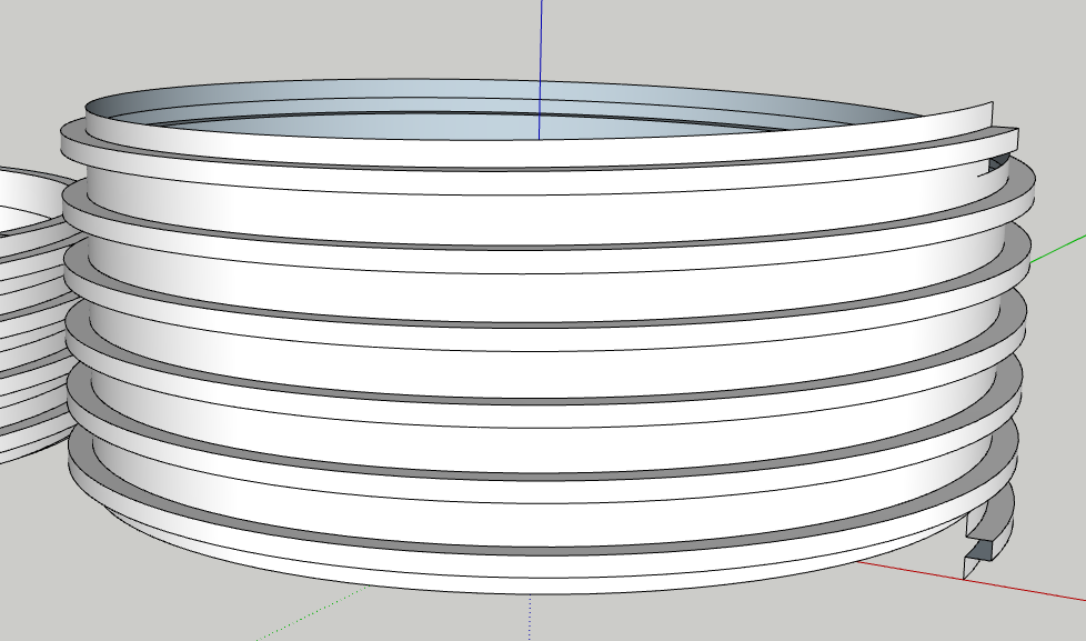
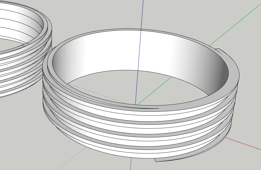
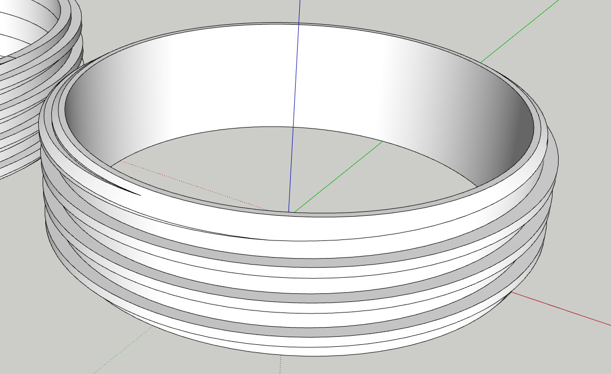
Could someone please take a look at this? I’ve spent over three hours trying to model it, but when exporting to STL and uploading it into a slicer, the model comes out poorly. The centre is completely solid, and some of the threads appear stepped rather than smooth.
This part is meant to be a threaded insert for a pipe conversion on a portable air conditioning unit. I’ve been putting off modelling it because I knew it would be challenging. The threads are square to match the adaptor, and I’ve modelled the male end slightly undersized.
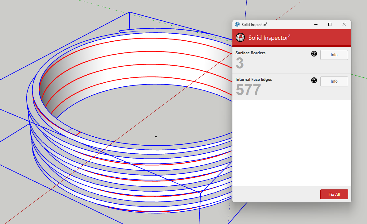
I’ve never had much success modelling threads in SketchUp, even though I use it extensively. At this point, I’m starting to think that for anything threaded, I might need to learn Fusion 360. I followed a YouTube tutorial, but once the thread is generated, Solid Inspector no longer recognises it as a solid. I tried scaling up and down while modelling but had no luck.
Honestly, I’ve given up for today—it’s just taking far too long.
I thhink you would have better success if you set model units to meters and made the model as if millimeters were meters. That would help to avoid issues with short edges and tiny faces. No need to scale the model down before exporting to .stl either.
You could go that route but I don’t think you should have to.
I’ll see if I can make a suitable example based on what I can glean from your model.
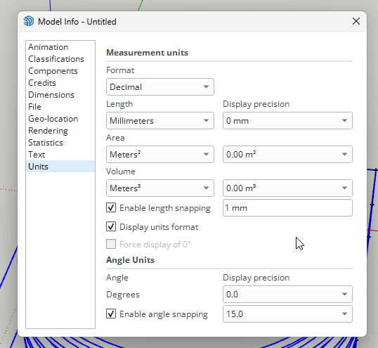
BTW, You should turn off Length Snapping and increase Display Precision, especially for modeling things like this. Those settings should already be made for your personal default template.
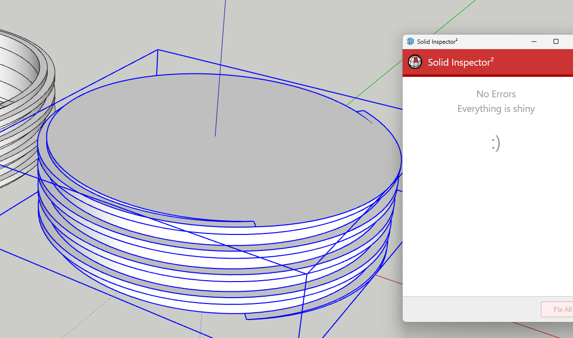
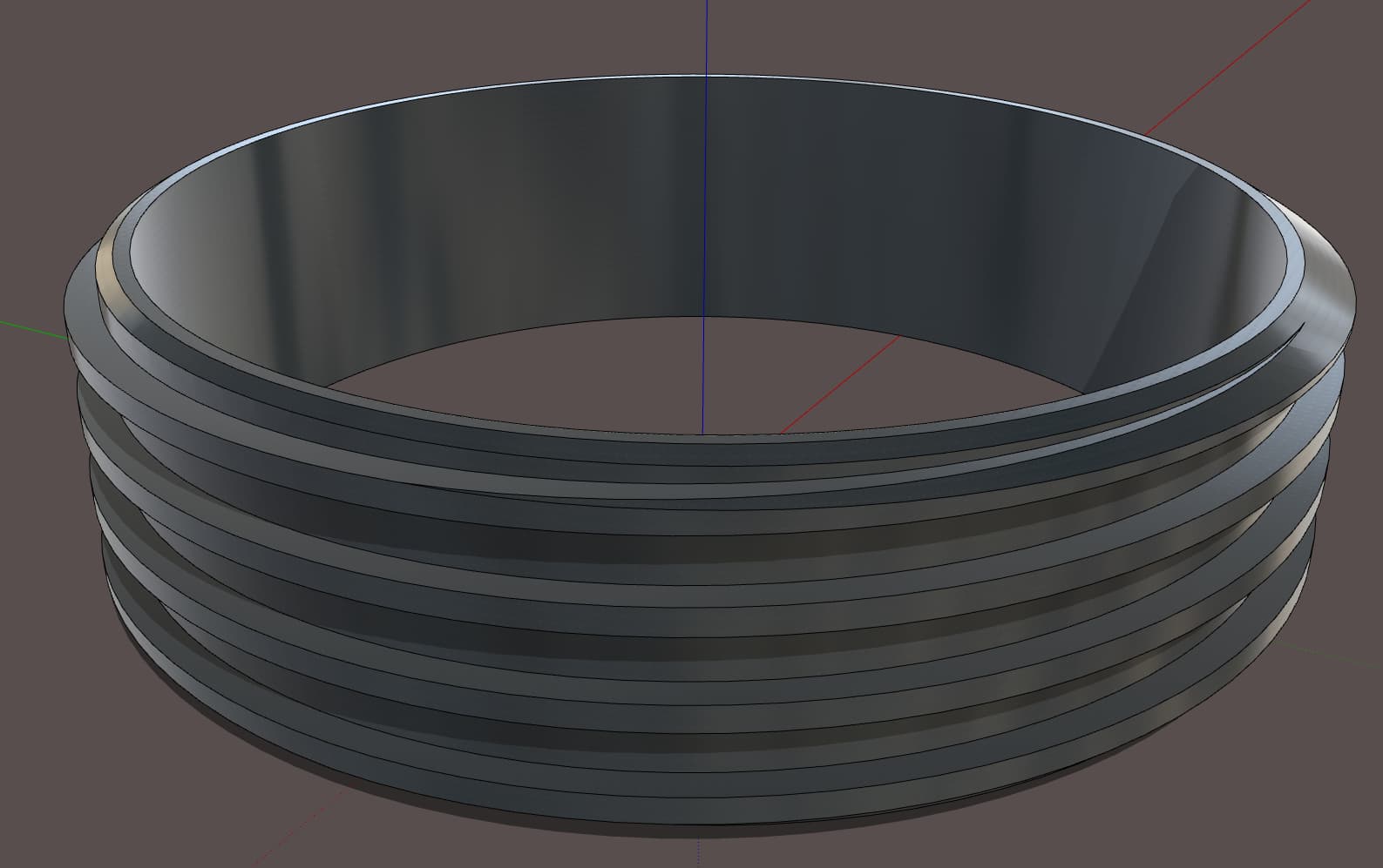
I saw the errors Dave showed, and Edge Tools and Solid Inspector couldn’t fix them automatically. I manually deleted a bunch of internal edges, and healed a couple of holes. Then Solid Inspector was able to fix the remaining issues.
I guess since Colin fixed your model, you probably don’t want a tutorial but since I made the screenshots, I’ll upload them.
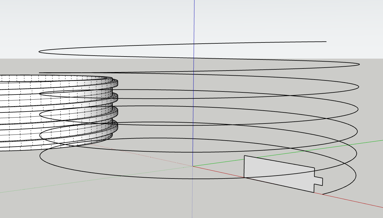
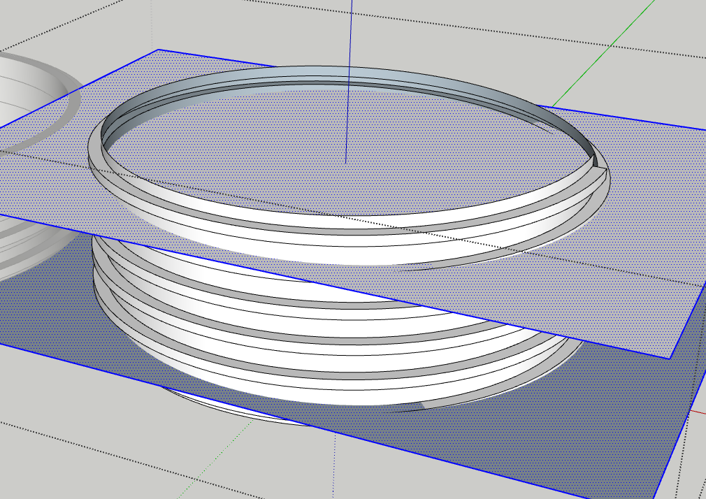
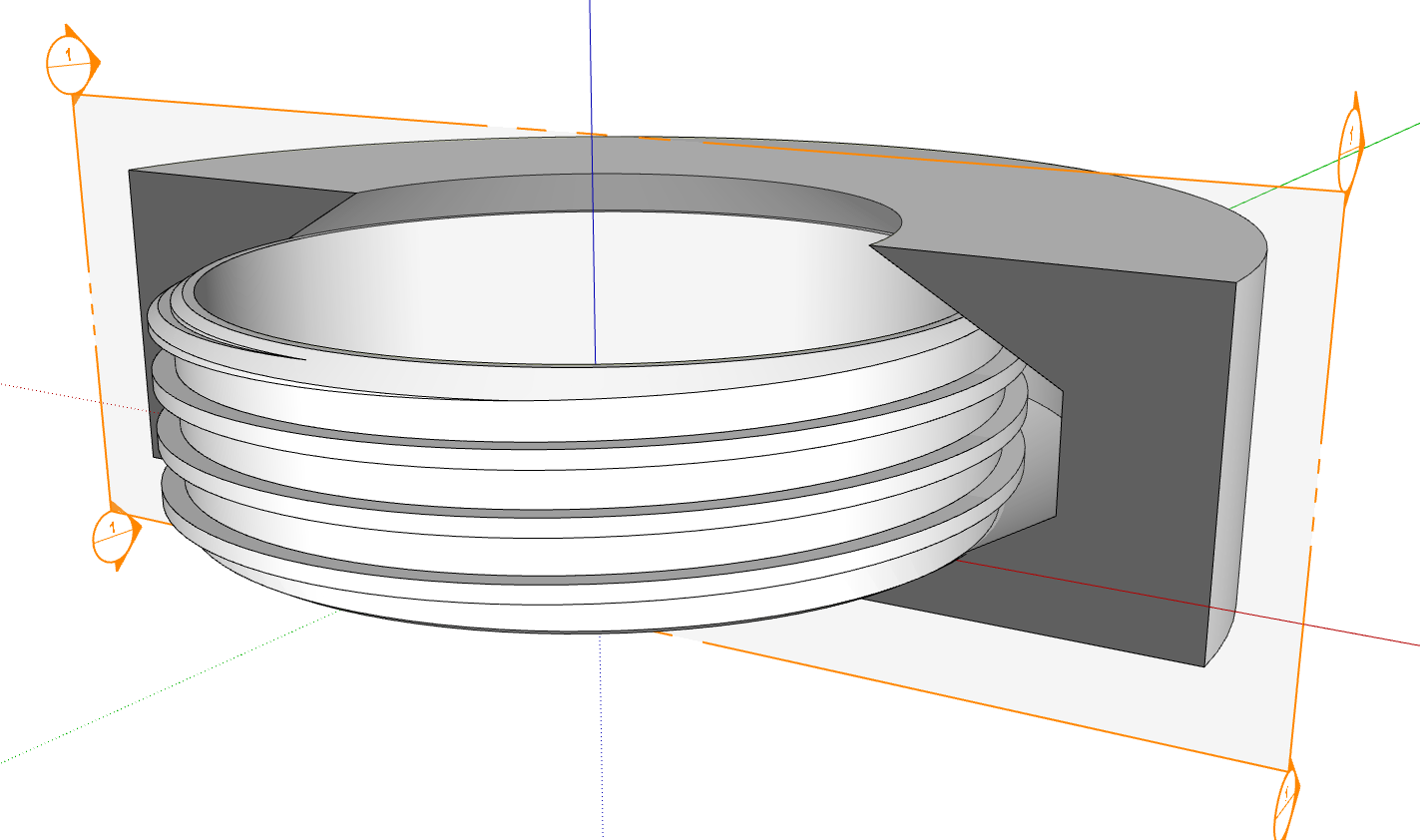
Setup the thread profile and helix. I make sure the original helix doesn’t end up incorporated with the extrusion as this makes cleanup simpler later. Note that I’m not trying to model the central bore at this point. There are a couple of extra turns to make finishing the ends easier.
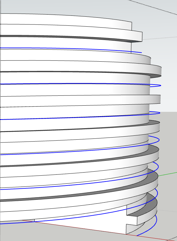
Using Parallel Projection and the Top view I select and delete the interior geometry leaving use the thread surfaces. Then I select the geometry and use Auto Weld to weld all edges that can be welded and I erase the unneeded edges in the trough of the thread.
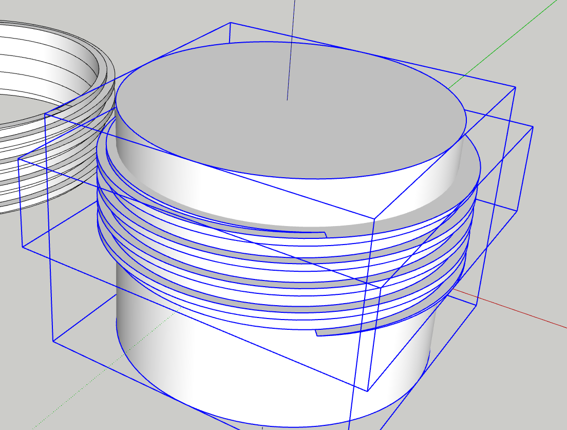
I created another “cutter” to add chamfers top and bottom and use Eneorth Solid Tools to trim off the corners. This makes the screw thread die into the body more cleanly.
Thanks, I probably need to try harder with the solid inspector. I was using it but i didn’t want to go down the road of fixing a F up as I thought the modelling was wrong. I was trying to get it perfect in one go.
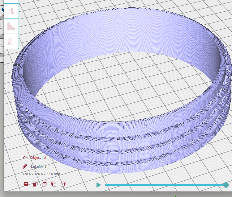
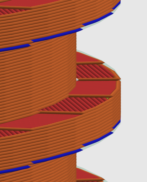
I have just put it into a slicer to check the thread and the threads looked stepped which i guess fall into the layers. Has anyone had any success with large threads like this? Will this come out terrible on the printer? I.e when i screw it in will be awfully rough due to the steps?
I haven’t had any problems with the steps in 3D printed screw threads. There needs to be clearance n them so they will go into the internal threads. The steps shouldn’t be a problem.
Thanks, for the detail. I was basically doign what you did up to the removing the internal geometry and using a cylinder inside the solid to drill. I will use this tip next time. I will also try the Eneroth solid tool, iv never used it before. I normally ise Bool but i find i get weird results sometimes.
Nice work, it amazes me how people get around problems like this thinking outside the box.
Just out of interest, im never used fusion 360 but i use AC regularly. How easier is it to model this thread system in Fusion? I use SU alot for work etc etc but im thinking about learning fusion also. I know SU can pretty much do anything fusion can but what is the difference? pros and cons? is it worth having it as another tool in the box if needed? I have a love hat relationship with SU. I do a lot of 3D printing and it is mostly very good.
I can’t tell you with certainty. It’s been a long time since I tried F360 but when I did I found it very clumsy and gave up. SketchUp works fine for all the machine parts I need to model.