Make sure you either click the left mouse button at 90deg or type 90 before hitting enter.
Thank you, it worked that time.
1 Like
Now I have all the dimensions, I want to make this 3D.
Some of it will be like a triangular prism, but with the very top either flat or rounded (as in the case of the lines in the top piece) and some more resembling wedges.
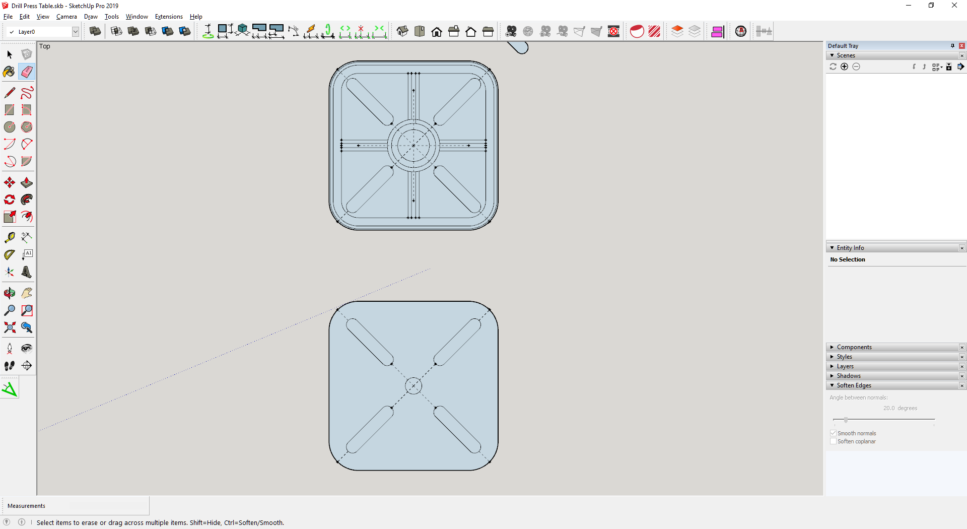
How can I achieve this in SketchUp? Do I use push/pull or an extension? How do I dictate exactly how it happens?
Also, I made the individual quarters into a component. Is there a way to push/pull multiple parts that are the same at the same time?
For example, I want to make a kind of triangular prism by pulling the highlighted part but want it to create triangles in the space between the next two lines:
These are very fundamental issues, have you spent much time learning the basics?
1 Like
I have over a long period of time, if I have forgotten something then I apologise.
I can’t follow the normal process with this because of the round corners:
Cutting a 3D shape out of your model
You can also use the Push/Pull tool to cut pieces out of your model. This action is handy in all sorts of instances, such as making a doorway, creating an angled roof, or cutting out a notch for a fastener, as shown in the figure.

Follow these steps to subtract volume with the Push/Pull tool:
- Select the Push/Pull tool (
 ) or press the P key.
 - Click the face you want to push, as shown on the left in the following figure.
- Move the cursor in the direction you want to push. You can push partway into your model to remove only some of it, as shown on the right in the following figure. If you want to completely the remove the content, drag until you see a message that says the offset is limited.
Tip: To completely remove the content, the face that you push must be parallel with the face on the opposite side of your model. If any lines divide the opposite face, you need to erase those lines before you can cut a hole through your model. To see examples, watch the video at the beginning of this article.
- Click again to finishing pushing away the content in your model. To set a precise distance, type a number and value and then press Enter .

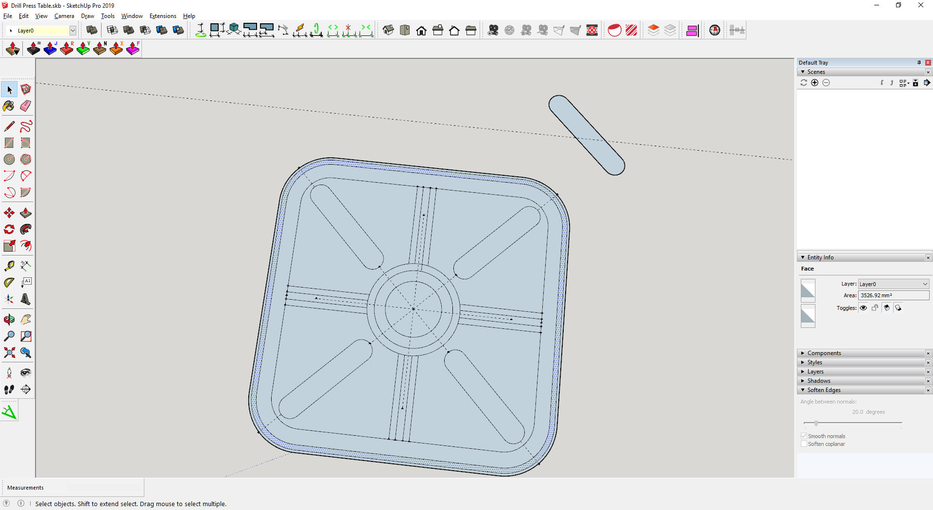
I don’t know why push/pull seems to randomly create solids and other times hollows.
Still no further forward unfortunately.
I have drawn a line and pushed the one part to the height it is. The line represents a slope which should follow around the entire shape including the curve.

How can I achieve this please? The follow tool did not work as expected. Edit: I created a solid face instead of just a line and that worked.
Going back to my other question, why does push/pull sometimes create solids and other times hollows?
I thought it was going to work for the whole process but for some reason I am getting an error even though all parts of the drawing were the same during design prior to push/pull.


Think I may have pushed it too high in this case on one part.
Fixed that but still a problem:

Yes, you need a face for FollowMe tool, technically, still no solid (a face has only two dimension).
When you have a face that is isolated (no connecting edges or faces) it is pretty clear that a pushpull would create a solid based on that face, but when you have (multiple) offset perimeters, the algoritme to determine how the inside and outside are interpreted need a little help from the user.
Thanks Mike.
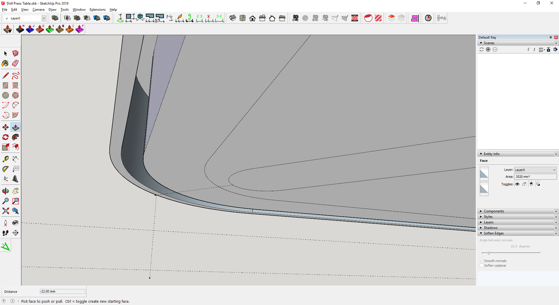
Can’t understand why this part is giving me such problems:
Drill Press Table.skp (549.3 KB)
I can’t see what is different about that corner compared to the other three:
Even when I can get it to follow the curve completely, it ends up with lines unlike the others.
Generally, this means that the path which FollowMe was tracing had an “arc” which had been exploded (for whatever reason) into its individual edge segments prior to invoking FollowMe. When FollowMe encounters the vertex between two edges that are not welded together into a curve or arc or circle, FollowMe marks the new edges that are generated (to create the adjacent faces) as not-soft and not-smooth. Conversely, when FollowMe encounters a path vertex where the two adjoining edges are part of the same curve/arc/circle, FollowMe marks the new edges that are generated (to create the adjacent faces) as soft and smooth.
This is similar behavior to how Push-Pull behaves when operating on a polygon vs. a circle, for example.
Upload the 3D model of your table.
I’m trying to understand how you are planning to use this on your drill press. Are you showing the top surface or the underside? A typical cast table would have ribs where you have channels and through slots on the diagonals.
If you’d told us a week ago that you wanted a 3D model of this table, I would have suggested that you draw 1/4 of the table as 3D before adding the slots, holes, channels, etc. And then rotate/copy as you did for the 2D version. It is usually much easier to start out thinking in 3D and then add the details than it is to spend a lot of time thinking only in 2D as in your example.
2 Likes
Thanks for your replies.
I want to see it in 3d so that I can visualise how a drill press table will connect to it and it’s also a good excuse to practice using SketchUp. It’s better to record dimensions this way for me in all three axis as well.
I’m a bit puzzled at the moment trying to understand why sometimes SketchUp puts lots of lines on circles when they are pushed and it looks like my model is a bit of a mess as a result. I don’t know why they would have been exploded when I have not instructed this to happen.
If you could please have a look I would be grateful.Drill Press Table.skp (542.1 KB)
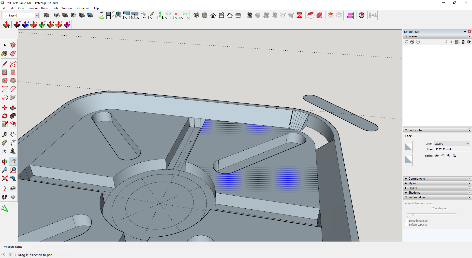
I have drawn the top and bottom and plan to combine them after I have extruded the bottom as in the file attached.
So as I said, it would be better if you start out thinking in 3D instead of 2D. When you start out like you are doing a 2D drawing as you would on paper or some 2D CAD program, you make things difficult because you are adding details at the wrong time. As with the2D version I showed you last week, since the table is symmetrical in both the X and Y directions, you can save yourself a lot of work by modeling only one quarter of it. Note: I did my best to decipher what your drill press table looks like based on your model but I redrew it from the beginning.

From the back left:
- The raised edge of the table is easier to draw using Follow Me so I drew a path and a profile.
- After Follow Me.
- Now that there’s a 3D shape to work on, layout the details. Since the slots and central hole go through, there’s really no need to lay them out separately.
- Push/Pull opens the slot and the central hole.
- Add the ribs and the post.
- Rotate/Copy to make the other three quarters. Erase the coplanar edges, soften any other edges, and make it a component.

5 Likes
Hello Dave, it’s clear that you are very skilled and I always appreciate your input.
It took me a long time to put the design I showed you together because of all the measurements. To start again in this way would take me a very long time.
I know in the long run it would benefit me because practising the concept you have explained would be beneficial.
For the purposes of this example, is there not a way to fix the problems I have with the circles without starting again?
You can soften the edges on the cylinder but the rest of your model has enough problems that fixing it will probably be more work than starting from scratch. I guess it’s up to you, though. If you orbit around to look at the other side of the table you’ll see you are missing what would be the top face of the table.
At the very least you could draw the outside shape of the table and make that 3D and then copy the lines from your layout onto it.
What I showed is all very basic modeling using only the most fundamental tools. It’s straightforward, efficient and results in an accurate model assuming the dimensions you have are correct.
2 Likes
In case you couldn’t tell, I did actually follow your instructions and built one quarter before duplicating it and removing the splits in the model that I shared. At that point it was fine and there weren’t any problems.
I find it very frustrating how easy it is to mess up a model and then even more so trying to fix problems, which sometimes is impossible.
I am going to try again the way you have shown. What I can’t tell from your image is how you got the shape right around the outside with the rounded corner in design 1 without drawing it as a square first etc.
A big thing with the modeling is getting the right order of operations right. As I’ve said, with a 3D model, it’s best to start thinking in 3D instead of thinking in 2D and changing horses mid-stream. Your process of starting with a 2D face and dividing it with all those edges is the basis of your troubles.
I drew a path with an arc at the corner and the cross section of the table. Then used Follow Me to create the shape. Basically in one step that part is done.


