Yes, I’m a newbie (sort of, I think that this is my 3rd time restarting with sketchup, so I have a little experience going back to sometime before 2010). I’ve been using it to model simple stuff I’m building and intermittently try to just draw something just for practice.
This time I’m trying a bolt. I’ve tried it a few times now. Current iteration I’m drawing the hex head, and then using the subtract tool to subtract a cylinder with a cone cut out of the bottom of it to chamfer the edges of the bolt head like a real bolt head is chamfered.
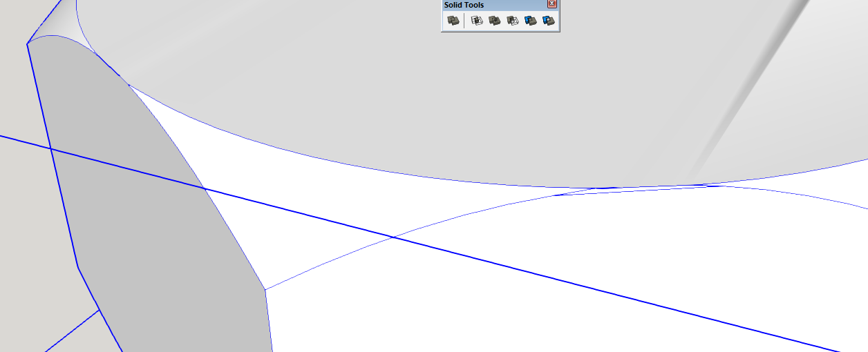
When I do the top it works out mostly OK, but 2 faces (not opposite faces, but with one face separating them) have a bit of an artifact from the subtract. What is it/what caused it/how do I get rid of it? (you can see it in the top curved edge of the selected face in this pic):
2 opposite faces of the head were created half closed and half open. I can close them by drawing a line across them but I cannot get rid of the geometry, you can see the 2 lines on the face in this pic, and if I delete them the face opens up again. Again, what is it/what caused it/how do I get rid of it?
Finally, this is the one that is driving me crazy, this is the reason I’ve re-drawn it a few times, have tried multiple different ways of locating my cylinder/cone for the subtract… I can’t get the subtract to work a second time correctly.
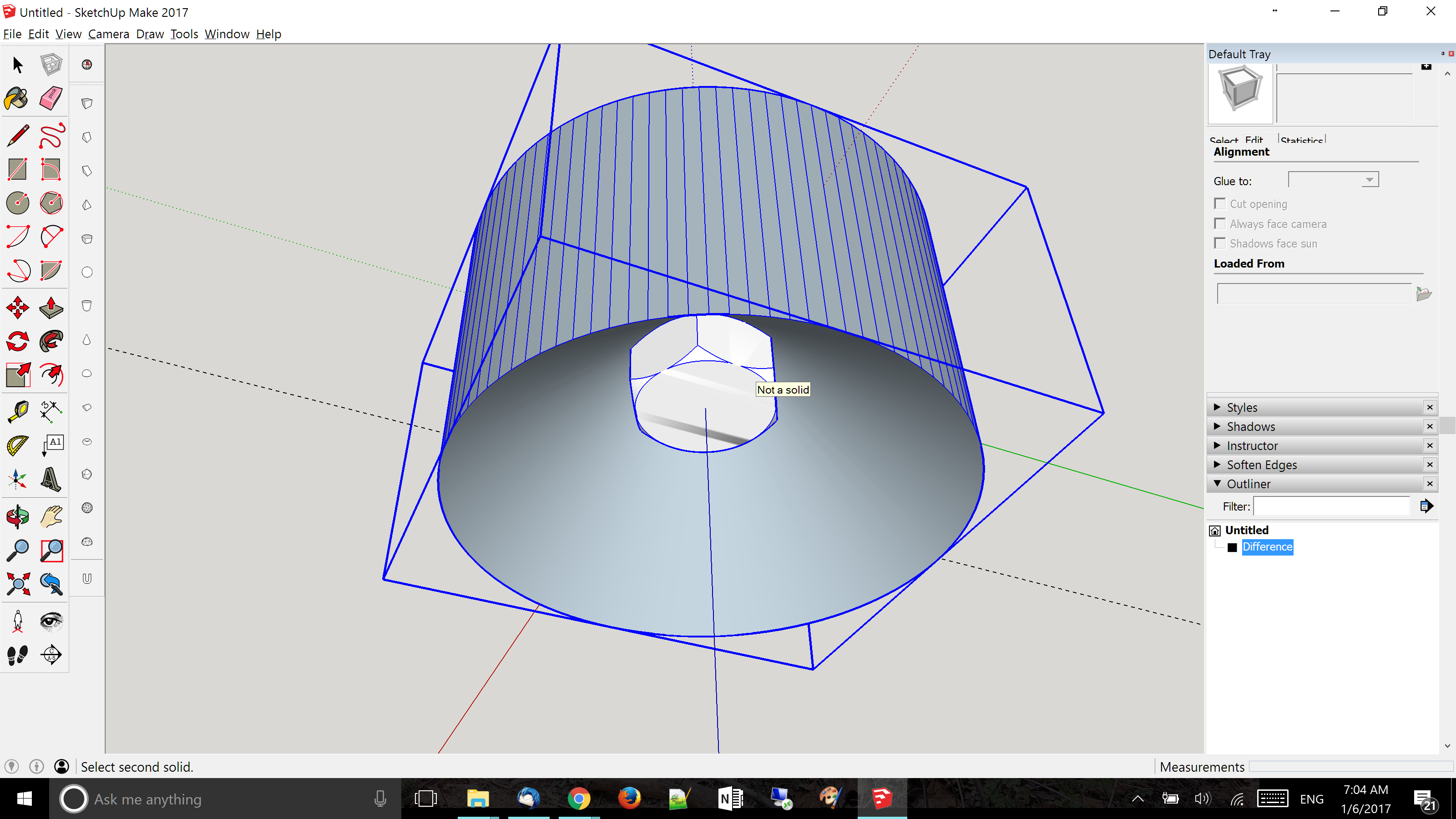
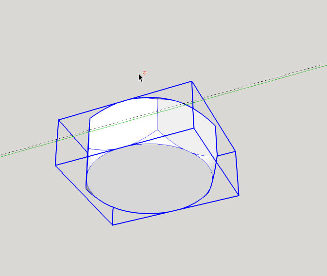
I’ve tried copying the first cylinder and then flipping it over and I get an error that it’s not a solid even though the one that I copied from worked fine. I would love an explanation for that, but I’ve gotten around it by re-drawing it and when I try it again I get that the bolt head is not a solid, if use the solid inspector plugin to check the bolt head i get that it’s nested and cannot be fixed automatically. If I go into the outliner and check it I don’t see anything nested, I just see a “difference” that cannot be expanded. I think that it’s treating it as a component in a group (shouldn’t that still work?), and if I copy it out, delete the original and then re-paste it and make it a new component (I would love to know how to fix it instead, not sure you can do that in a more complicated drawing), I can get the the solid tools to see both solids but the results don’t make any sense, I get this choosing them in either order, it basically looks the same but the shading has changed and nothing is a solid anymore:
If I use the other solid tools they look like they’re working as expected, intersect gives me the corners that I’m trying to chop off and union looks like it made it one thing, the last 2 I honestly am not sure what they’re supposed to do.
If it helps I’m attaching a copy of the current sketchup file (it will show the current problem but the previous stuff is long gone since I fixed the last issue before this one by copying out the results and deleting everything else)
The artifact comes from the way you have the chamfer intersecting the sides. You’re running into SketchUp’s tolerances. The endpoints of the segments are so close together SketchUp considers them to be coincident and winds up distorting the shape.
Try drawing it with the circle on top not meeting the hexagonal perimeter.
I’ll try scaling it to fix the first 2 artifacts (I’m assuming that you just choose scale and use 100,100, then when you’re done scale again and .01,.01?), but what about the second subtract not working right no matter what I try?
Yes. The thing both Anssi and I wrote about scaling the model up is important. Try that. But also consider that the way the curves are intersecting will create issues because endpoints are so close together.
Notice the garbage on the top. It looks to me as if the chamfering group also wasn’t centered on the hex.
I just spent most of last night drawing, redrawing, drawing again, starting over, googling, youtubing, googling some more, redraing (you get the idea).
I scaled it 100x and then scaled it back down .001 and got it done with no issues in 5 min
Glad you got it sorted. SketchUp’s polygon representation of circles and circular arcs can cause strange effects when a circle passes close to another entity. See this recent topic for discussion about what happens and why scaling up usually avoids the problem:
Even scaling down to actual size can bring back the “annoying” issue although it works for you this time. But you need to understand the cause of these issues in general. Turn on ‘HiddenGeometry’. See where endpoint may end up that close that their separating distance is less than **) 0.01mm. In that case they’ll merge into one endpoint, dragging edges (hidden) edges with them. Even when scaling down. This distorts your geometry.
Actually, thinking out loud, is it possible to get sketchup to just scale the dimensions, and let you draw at 10x or 100x rather than scaling back and forth? Or at least how do you get it to keep the origin in the same spot when you scale back and forth?
That kind of thing is what I was thinking about when I just asked if there is a way to draw at 10x or 100x and just have the dimensions appear at .1 or .01x. This would be relatively painless if I was using the metric system, just use 1cm in the place of 1mm, or 1m in the place of 1cm and you have 10x and 100x scaling
To be clear: there is a difference between drawing the whole model at a larger-than-real size (and perhaps scaling down to real size when completed) vs drawing at real size but creating a temporary enlarged copy when needed. You just delete the temporary copy after the subtract, no need to do any down scaling.
Also, there is no facility in SU to draw at one size but fake dimensions to indicate a different size (well, not quite true: you could edit the dimension text to say whatever you want, but that is going to be more work than rescaling the model!).