Its easy when lines are perpendicular but when complex then its a nightmare.
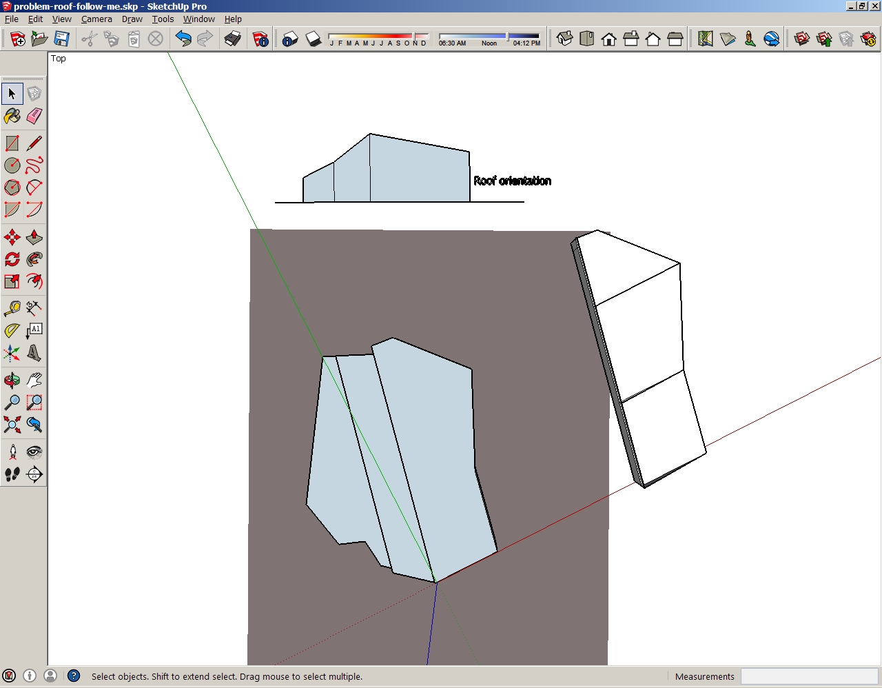
I’m trying do make a roof for my building with the “follow me” tool but it just doesn’t work. Tried with the “move” tool but it makes fold lines on the roof where there aren’t any. Here is the example of my problem,
http://www.1-na-1.com/sketchup/problem-roof-follow-me.jpg (with orientation of the roof)
here the file I’m working on
http://www.1-na-1.com/sketchup/problem-roof-follow-me.skp
Can anyone help me? Explain in steps how to make the roof for the building.
Hi,
If I’m looking at this properly. . . I like what your doing with the trusses that you’ve drawn in. and to continue on with adding in the roofing surface – I’d just work with the Line tool, and simply draw in diagonal lines between the opposing corners of each pair of trusses. That alone will get SketchUp to create the surface between them. . . albeit with triangular shapes – but you’re not going to be able to avoid that, given the roofs design. You can always use the eraser tool if you must hide the diagonal lines which are going to happen in the roofing surface.
None of the sides of the three main volumes you have modeled thus far are parallel, this means that you can’t add a quadrilateral roof over any of them.
This fact of geometry applies in SketchUp AND the real world !
If you actually built this you’d need a ‘valley’ to allow the roof plane to ‘twist’ so that it could meet all of the edges…
As @JimD explained you need to ‘triangulate’ the roof forms.
The direction of that ‘valley’ is your choice - but one is necessary… unless of course you revisit your plan and start making some parallel walls [your carpenter/roofer will thank you for that too!]
The attached screenshot shows the edges I added ticked yellow - then the roof forms as you hoped…
It’s difficult to tell from the blurry GE image and your partial model what the roof actually looks like.
Here’s my guess. Click through the scenes in the attached model.
Multi Pitch Roof.skp (116.0 KB)
Tip:
Align the drawing axes along the length (ridgeline) of the building.
Once you have traced the building footprint; turn off the Google Earth layers.
So there you have it…
My way to keep the roof’s eaves/ridges/verges as your 3d box - needing valleys etc…
OR @Geo’s solution which keeps the cross-section and gives single roof planes - which of course means that the eaves/ridges/verges etc will not be as your 3d box suggested…
That might actually be what you expect - but again remember that the changes of direction to sloping eaves etc are tricky to detail effectively in a real world solution…
Just because you can model it in a computer doesn’t mean it’s a good idea in reality…
This is exactly the result I need as it is in real life, its the building I erected in 2001. Thank you. Now I need to first understand what you told me and make it myself.
Also thank to all others who have suggested solution to the problem.
@Geo. I can’t make the drawing if there is the GoogleEarth orientation map under the object.
@TIG. Your suggestion is the only way I could do it. Thank you very much. Here is the finished drawing. http://www.1-na-1.com/sketchup/problem-roof-follow-me-solution.skp