@DaveR is the best there is, in my experience, for advice about Intersect faces. He has a good process for it.
Thanks John.
@EosDawn, it seems to me that if you just want the pocket holes in the board, you don’t really need them to be hole cutting components. Instead, make them solid components and use Subtract from Eneroth Solid Tools or BooltTools2 (Not the native Solid Tools) to “drill the holes”.
Exploding the components John has worked so hard on eliminates their hole cutting property. That’s only an optical illusion that exists while the component is intact.
Make the pocket hole drill as a solid component with gluing properties and make it easy on yourself. If you really feel the need to make it adjustable, that could be done in a Dynamic Component although that would add a bit of complexity and a few extra steps. Instead, I would create a collection of pocket hole components set up for different stock thicknesses and choose the appropriate one for the stock you are drilling. It won’t need to be a very large collection and you could make only those you need and add to the collection when the need arises.
This will eliminate all the faffing about with Contexts and intersections and erasing stuff.

1 Like
So, using this method, I would guess the holes will be nested components within the board component, is that right? How will Cut List report the holes? My goal would be to show the holes with dimensions for placement. Would prefer to omit the holes from the Cut List.
Cutlist reports the bounding box of the component. This method won’t change the size of the bounding box. It would be the same as punching a hole straight through the part.

So, the bounding box size getting expanded (through the use of other methods) would cause problems with Cut List. Starting to understand.
Would prefer to use native tools, but will give the Eneroth extensions a try.
Would using John’s components with intersect with faces (after using explode/cut/paste-in-place) affect the bounding box size?
If you add anything to the component that isn’t the “board”, that will create erroneous dimensions in the cutlist. So even having the screw in the component would be a problem. Actually if you leave the screw as a component inside the board component, the board won’t be reported anyway because it isn’t the bottom level component, unless you create a tag/layer for the screws and turn that tag’s visibility off first. (extra work since you don’t really need the screws anyway.
I generally prefer native tools, too, except when they create more work for me later on. The native Solid Tools don’t respect components. They convert the components they modify into groups and don’t modify the other instances of the component. Eneroth Solid Tools do respect components.
Only if you aren’t careful to remove all of the excess geometry.
If you go back to the thread where we went through exploding and intersecting you would find that the result would have been what you wanted.
But you never mentioned there that you wanted it to work with cutlist, it always seemed like you wanted to retain the component structure rather than remove it as you have now explained.
1 Like
How do I determine the bottom level component in an assembly, outliner? Using a hole (solid) in a board (solid), I’m guessing this is referred to as “nested components”? Cool idea of using layer visibility to control what Cut List sees.
And also cool, about Eneroth preserving the component attribute. less work, I agree. Had no idea the native solid tools converted components into groups.
Depends which version you use. If the ones with screws, whether or not you explode them, yes.
If you use the ones with just screw heads, no, again, whether or not you explode them.
Using Open CutList from Extension Warehouse, it doesn’t exhibit the behaviour @DaveR mentions of not listing a board with a component inside it.
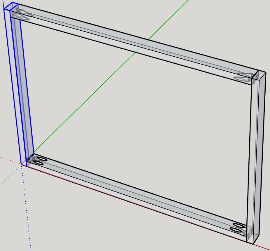
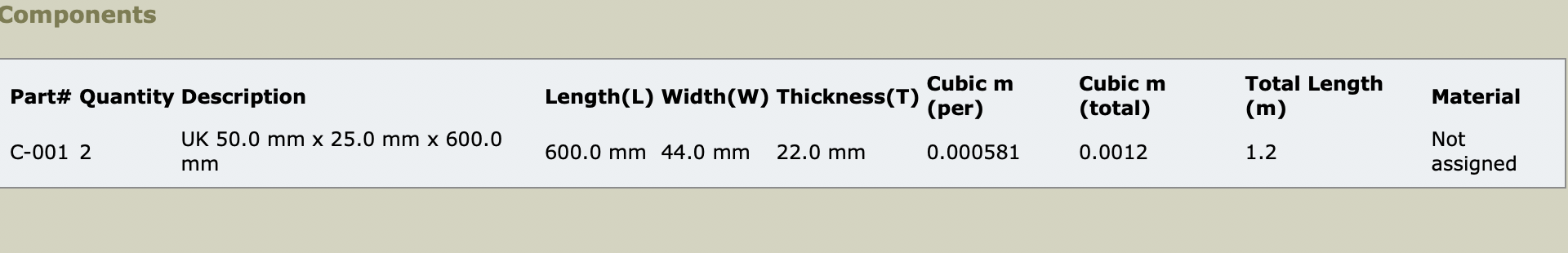
Here’s an example for a simple 2x1 frame using metric UK sizes of nominal 50x25mm or finished size 44x22mm, with two Kreg pocket holes at each end of two of the pieces.
And the Open CutList report (detail list only).

I left the Screw hole as a component. It would probably be better exploded to become part of the pocket hole, when it would not list separately.
Looking at the result, I can see that I need to set up Parts in Open CutList properly, which I haven’t done.
Will try the same CutList as Dave before I go to bed and post here.
You can look at Outliner to figure out component level.
My method doesn’t put the pockethole inside the board component so there is no nesting.
Don’t make the model more complex than it needs to be. Nesting components adds complexity. Only use it where it is needed. At least in my opinion, there’s no need to use nesting when adding joinery details.
Open CutList doesn’t seem to care that there are subcomponents in the board, but lists the board anyway - not just the lowest level components in it.
And Dave, a very small point of detail (and from your point of view showing a technique, not exact geometry, an unimportant one) the screw hole drilled by a Kreg bit in a Kreg joint jig doesn’t go all the way out to the face, but should (if the drill stop is positioned as they recommend) stop at least 1/8" (3.2mm) short of it.
Trivial thing to change in the components. I didn’t try modeling these components to be exact anyway. It was just to show the concept.
Agreed, not important in the technique, and easy to fix. Claire pointed me at it earlier.
Thanks John, did not know about Open CutList. For this application, OCL seems to be a better choice than Cut List. Was not concerned about the screws and holes but if they do not interfere with the OCL report, why not a more complete accounting. At the big box store, with the details of lumber required, is it not better to know how many boxes of screws to buy!
Tried again with the CutList you are using, Dave. With the same arrangement, as you say the board with subcomponents doesn’t get listed.
But although I designated kreg and screw as parts, they didn’t list either. Maybe I missed a setting to show parts, not just omit them from the dimensional listing?
No, it looks as if the default is to include them. Include [Parts] is checked but this list doesn’t include them.

I hardly ever use either CutList plugin, so don’t know if there is one somewhere in this one to list parts? I’m nearly sure I’ve seen an example that does, but maybe that was from another plugin?
Exactly, you hit the nail on the head. When this journey started I naively wanted to model every detail. Over time it became clear that all that detail bloats the model, affects performance and adds little value in the shop. Then I came to understand the modeling purposes for illustration and real world exactness. I am now leaning toward more illustration and less detail for my present projects. For instance, showing the position of the pocket hole (with dimensions) is more important than showing the screw details (threads per inch, etc.). Hope this makes sense.
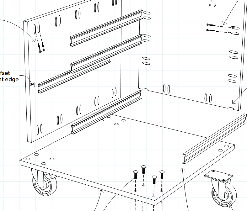
This is from a recent plan I did for a client. The pocket holes are just ellipses on the surfaces of the panels. They are not a component separate from the panels. There are no actual holes in the panels. Notice that the drawer glide parts don’t have the myriad holes that the real ones would have but they still get the point across.I don’t see any point wasting time and bloating the file creating geometry that won’t show.
2 Likes
Great example! Confirms my suspicion that by doing a very good job of illustration, the details can resolve themselves in the shop.
Off topic. I am modeling your footstool design (Fine Woodworking). My budget does not allow for hardwoods and I am considering MDF or Particle Board. I once tried to route Particle Board and recall it was a disaster. Would MDF (using pocket hole joinery, of course) be suitable?
Dave will know if it’s suitable. But if you are routing MDF, wear a good close fitting face mask to filter the dust. It’s mildly carcinogenic.
My footstool design? Which one are you referring to?
MDF would be better for pocket hole joinery than particle board certainly.
John’s right about wearing proper PPE when cutting termite ■■■■.