My model tram cab needs a hole in the roof before it can be printed but Sketchup make 2017 will not allow me to make a 1.5mm hole in the curved roof, so how do I make one please?
An additional question how do I add a copy of the file?
My model tram cab needs a hole in the roof before it can be printed but Sketchup make 2017 will not allow me to make a 1.5mm hole in the curved roof, so how do I make one please?
An additional question how do I add a copy of the file?
Drag the .skp file into your post.
To make the hole, you need to scale up a copy of the model - use metres instead of mm - then scale down before printing, or (depending on your printer software) import your model and tell the printer that units are mm.
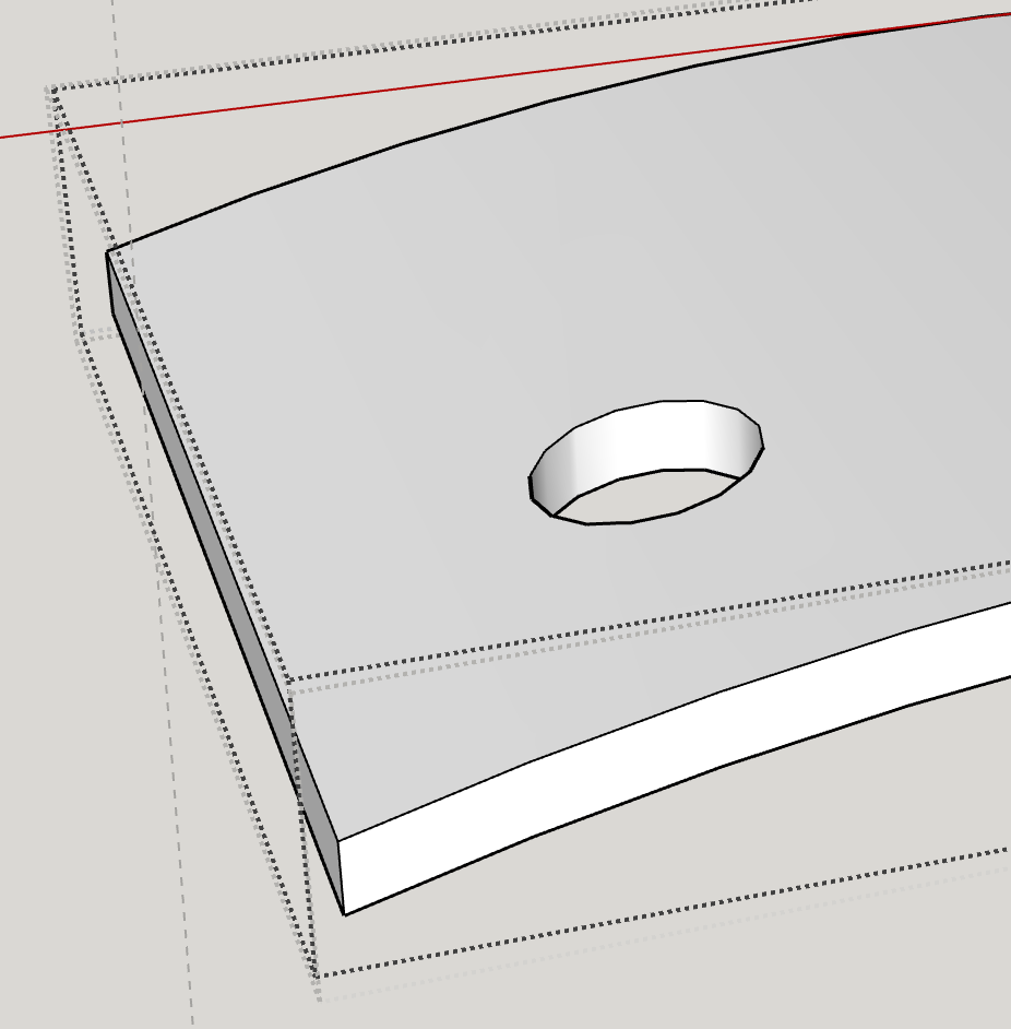
Push pull a cylinder from a 1.5m diameter circle, insert it in the right place, then Intersect Faces to create the hole.
Delete the surplus.
Thank you my file is here SM R No.7 cab 4mm.skp (1.3 MB)
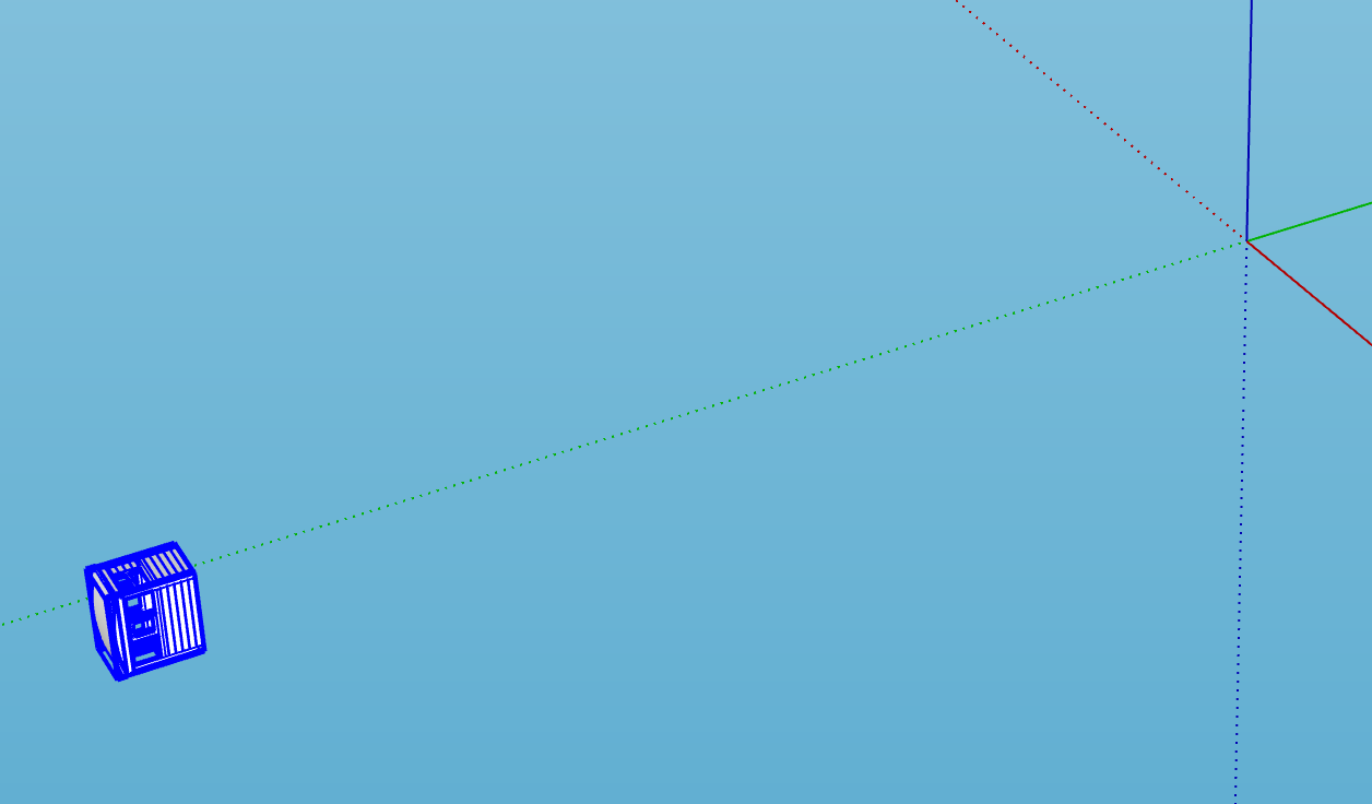
Why was the model so far from the origin, and on its side?
And where is the hole in the roof meant to go?
Make the roof into a Component (it’s only a Group at the moment) and make a copy and scale up the copy 100x or 1000x. Zoom Extents to see it.
Place it where you want it, with plenty of cylinder above and below the roof.

In Model Info/Components Fade rest of model UNcheck Hide, otherwise you won’t see the cylinder at all when you do the next step.
Open the roof for editing, and use Edit/Paste in place to put the cylinder into the roof context


Thank you John,
Gordon
Hello John,
Thank you for the very thorough instructions which i have followed but when I deleted the tube there was no hole in the roof so what did i miss?
Gordon
You possibly didn’t get the cylinder and the roof in the same context before running Intersect Faces, or if you did, you may not have had everything selected first.
Another possibility (it happened to me the first time I tried it) is that you didn’t start by making the roof into a component instead of a group. Edits to a copy of a group have no effect on the original.
A third possibility is that you didn’t copy the roof component before scaling it up, and therefore when you deleted the large copy, it was the only one.
I hope one of these suggestions helps you to get it right.
If you get completely stuck, put a cylinder of the right size in the right place, upload it here, and I’ll cut the hole for you.
Sorry john,
it isn’t working so I have attached a copy of the file for you so can you please put the hole in?
Gordon
(Attachment SM R No.7 cab 4mm.skb is missing)
Sorry john,
it isn’t working so I have attached a copy of the file for you so can you please put the hole in?
GordonSM R No.7 cab 4mm.skp (1.4 MB)
Just downloaded your model.
As I thought was possible, you haven’t made the roof into a component - it’s still a group, and you have three other copies of the group, again a long way from the origin.
Make the roof into a component was what I said to do first. Enlarging a copy of the group, then editing the large group, will make NO changes to the original.You have to make the original into a component first.
As Dave R said you have reversed faces. Correct them, if you want the parts to 3D print, and run the plugin Solid Inspector2 on the parts to check that they are solid
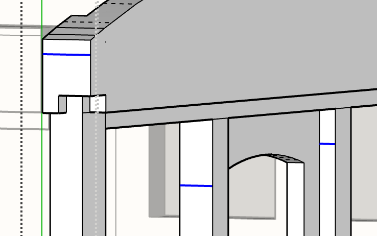
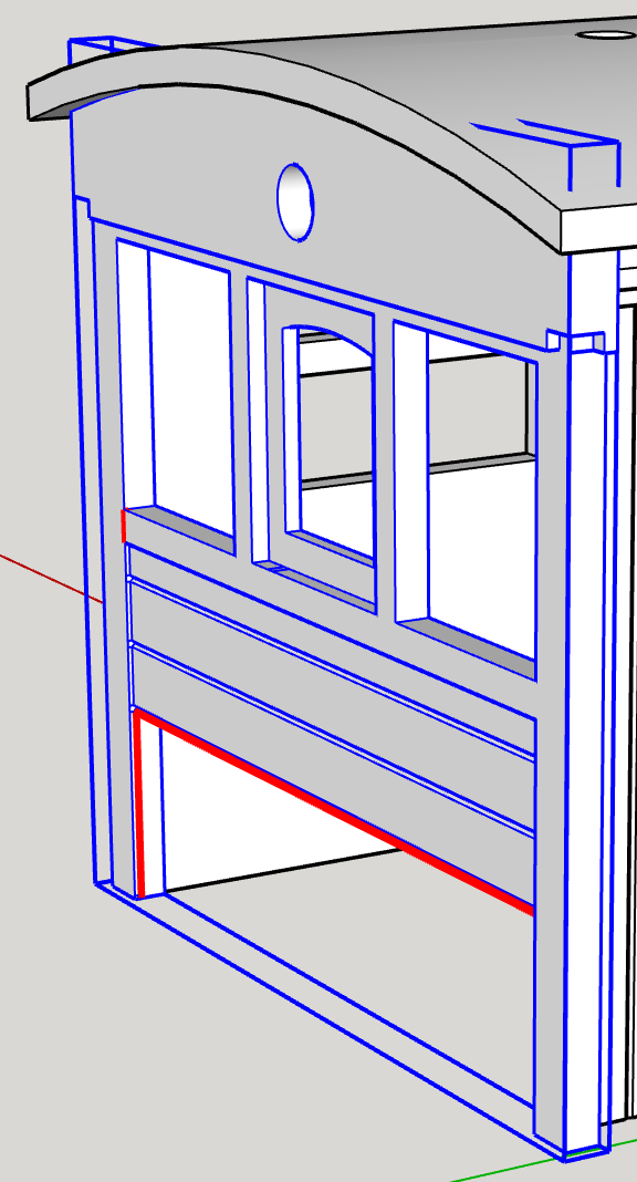
You have some stray lines in the end - highlighted in the image below. Delete them.
You have an odd split at the upper corner of the front (or is it the back? The one without the hole over the window).
…which I’ve fixed, but there’s something wrong with the way you have modelled that whole piece. If I click on one white face, and choose R-click/Orient faces, they come out mixed front and back faces.That suggests there are some internal faces, and SU can’t work out what’s supposed to be outside, and what inside. That probably won’t 3D print, as a result.
The curve of the roof doesn’t match the top of the ends.
You need to redraw either the ends to match the roof, or the roof to match the ends, or model both to a correct arc radius - perhaps 44mm? I don’t know what value it’s meant to be.
The lower edge of the roof and the top of the end with the hole aren’t any particular radius, and are different. The former is 48.265625 mm, the latter 43.259468 mm. The arc isn’t continuous - it has two parts along the top, and the extreme ends aren’t part of the arc - looks as if you might have added those separately.
And the top of the other end is no longer an arc, but a curve.
You had several chunks of hidden geometry, not close to the origin, visible when you Zoom Extents. I’ve deleted them, as they seemed just to be two lots of connected stray lines.
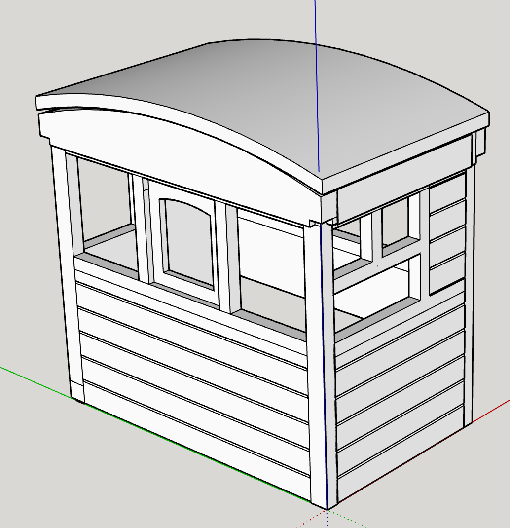
Here’s a partly cleaned up model.
In general, I would recommend making components rather than groups by default, and name them as you go.
It might be worth starting some of the parts again.
The axes of your groups aren’t the same way round as the model axes. Once you make groups into components, you can R-click and Change Axes.
Learn to model accurately, and get your axes and your components and model the right way up = red to the right, green receding into the screen, and blue up.
If you haven’t studied the Fundamentals of Sketchup at learn.sketchup.com, it would be worth your while to do so.
I haven’t put the hole in the roof, as you’ll only have to redo it when you remake the roof and the top of the front and back to match.
Thank you for those few kind words John but as I am a new Sketchup user I am still learning how to build a model…
Fair comment - and it’s coming along as you get more practice.
Stick at it. You’ll get there.
Thanks John,
Gordon
Helllo John,
I have followed your instructions up to putting the pipe into the roof but how do I, after selecting all, Intersect faces/With context to get this: and what is a R-L crossing selection

I am finding my way!
Gordon
Either use Ctrl+A or triple click on the roof to Select All when you have your model looking like the image you show. Then R-click and choose Intersect faces/With context .
That will create the intersection lines you can see already in your image.
A R-L crossing selection is one name for using the Select tool to select everything which its window crosses, whereas a L-R window selection only selects anything wholly within its window, or within the projection of the window along your viewing direction.
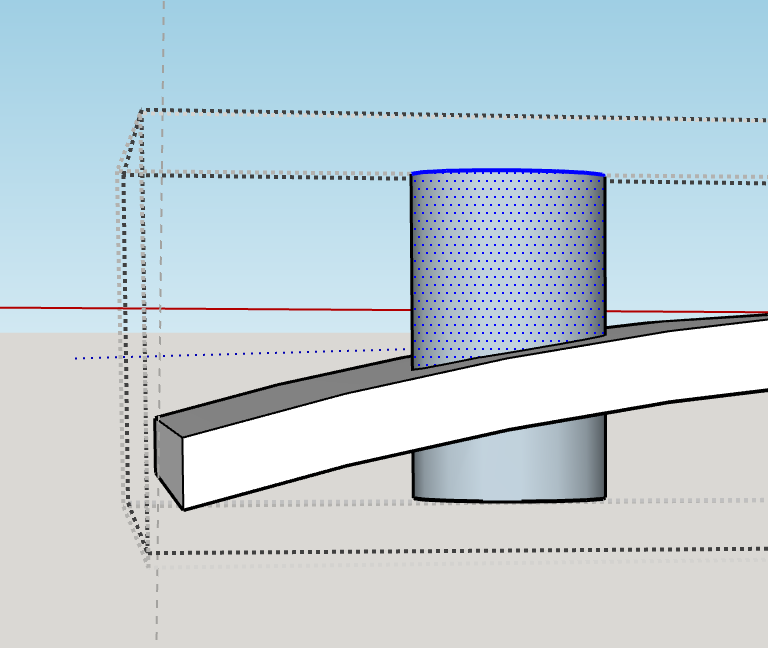
So if you look at your roof and cylinder from the side, to select the top of the cylinder in order to delete it, you should use a R-L crossing selection to get both the sides and the top of the cylinder. My screen capture can’t show you the selection window - it disappears when I start the screen grab, but it’s the rectangle you draw when using the Select tool (started by pressing Spacebar) and dragging the mouse with the left button held down.
Like this:
Delete that bit, and repeat for the part of the cylinder below the roof.
And you should end up with:
Delete the face in the opening top and bottom, and you have your hole.
Hello John,
I am obvoiusly doing something wrong with the hole. so can I take you up on your offer to make the hole for me the tube is in the correct position in the roof…SM R No.7 cab large.skp (1.4 MB)
Hello John,
I have just realised that the hole was too big so have redone the file which is attached SM R No.7 cab large.skp (1.4 MB)
Gordon
Well, it still isn’t affecting the original size model when I edit the ‘large’ scale roof (only 10x scale).
The large copy is only loose geometry, not a larger version of your roof component, so when I edited it, it made no difference to the original roof.
I’ve redone it so that the hole is in original component as well.
In addition to doing that, I’ve deleted a couple of stray lines near the model when moved to the origin, I moved the roof into a central position over the cab, and got rid of an invisible but distant stray edge - I deduced its presence because Zoom Extents left a lot of space above and to the right of the visible model. To do that, I selected round the model, cut it to clipboard, then did Select All, and deleted the edge (which i still couldn’t see!).Then did Edit/Paste in place to put the model back.
I deleted the redundant components, and renamed the cab component to Tram cab, and renamed the roof to Tram roof, to get this.
One of the redundant components is the 3D Print component. I’ve deleted it. It contains huge amounts of information about 3D Printers you don’t have, and if you are lucky, a little about the one you DO have (or the printer you don’t have that someone else does, and will print for you).
Start any future models for 3D Printing in a plainer template, like Woodworking - millimetres. Just make sure that you don’t draw any parts larger than your target 3D Printer’s print volume constraints.
I ran Solid Inspector2 on each of the components. The roof is solid, but the far side of the cab has holes:
And so does what I think is the back, near the bottom of the corner pillar. I’ve tried to fix it, and failed - sorry. Looks as though you will have to redraw this, if you want it to 3D print.
|n fact, all the sides except the front have errors that Solid Inspector can’t fix. And the front (along the red axis) had stray edges, which Solid Inspector DID fix. The roof it solid (though because it has rather small edges in the roof round the hole, it too lost three faces when I first saved it), which I was able to patch.
I’d suggest you scale up the whole model x1000, and re-draw the non-solid parts using metres as if they were mm, then scale it down for your 3D printer.
If you haven’t yet installed the extension Solid Inspector2 from the 3D warehouse, do so now, and use it to check as you go that your subcomponents are each solid, and fix them if they aren’t, before you move on to the next. It will show you in red where any errors are that it can’t fix, and when you press the Tab key, will zoom to show you in details where they are - usually, where there are ‘Surface border’ errors, where there’s a face missing, or a corner not cleanly joined.
And you could use more subcomponents - for example, your front, back and sides are each loose geometry inside their respective components, and not quite accurately drawn at the corners where different pieces meet.
Much easier to get right in the first place if you made (for example) each corner pillar one component, the horizontal boards each another, and so on.
Sorry I can’t fully fix the model, but it’s getting better each time I see and examine it. The roof and sides, for example, now fit properly.
But I don’t think it would print, as it is.
As an example, I’ve remade the back using subcomponents, each redrawn over or redrawn from existing geometry, and all scaled up by 1000x, and included it in the overall model.
SM R No.7 cab large JWM.skp (152.1 KB)
And here’s how the model is now structured (as shown in the Outliner window)
I’ve given the horizontal boards in the back a flat inside face, as you had. Were the originals tongued and grooved planks? If so and you want that detail inside the cab, redraw them by pushpulling a cross section of the boards.
Thank you for all your help. The model with the T & G boards down to the bottom is the front of the cab which was drawn 10x finished size and the large roof is 10x larger again which means that the hole in it should be 160mm diameter not 16mm in the file I added to this thread. I now need to digest your advice and decide how to proceed with the tram cab.
After a great deal of redrawing from scratch, we finally managed to get a printable model, with this result:
Even so, the model is not technically a solid, either in the view of Solid Inspector2 (surface border errors) or of Sketchup (not a solid component). But it is good enough to print successfully. I can’t understand why it was so difficult to draw, even at 1000x scale (using metres for mm).
SM R No.7 cab large JWM.skp (347.1 KB)