I want to ask if is it possible to measure position of three components on the image or on the diagram, when I have the model from NASA rover curiosity dowloaded?
I am working with the second one, they should be identical.
The diagram I use is from the pdf here:
page 39.
I upload image of the diagram. I have added 3 blue lines showing the 3 components on the left side of the rover: 1) holder for antenna coaxial cables. 2) connector holder 3) some cover which looks like filter unit.
The reason why I need to located there exact position is that I have a bit problem to position the texture correctly (it has been deformed to parallel lines).
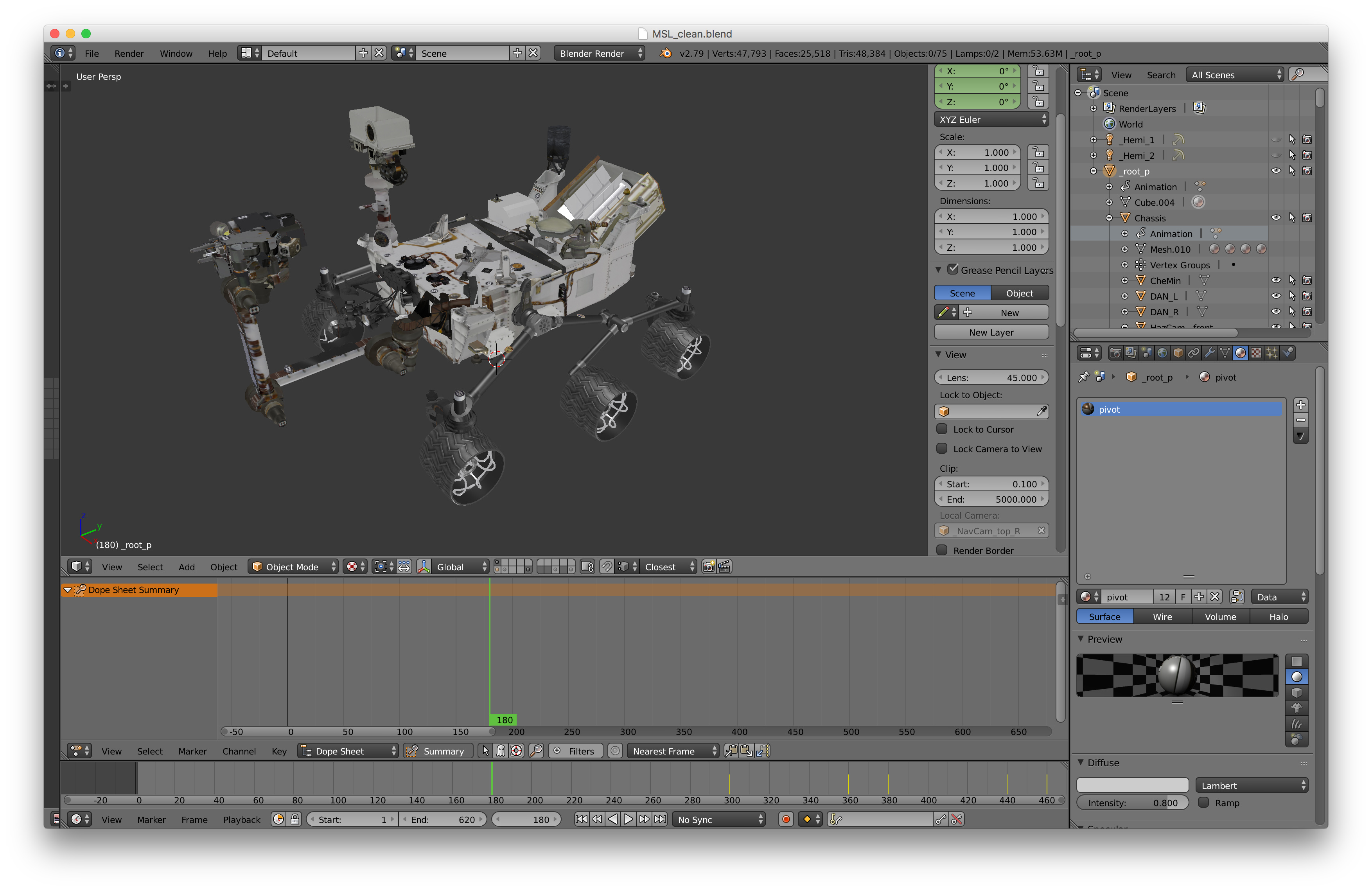
Also screenshot from my model:
The cables in the blue circle are shifted too much to left. I measured size of the crews on my texture is about ~7.5x7.5mm Same on opposite side. When, but it seems in needs to be narrower because the cables to High Gain antenna are too much in the left. Should be cca 10cm rightwards. So I am hoping that measures from the small components on the photo or diagram could help me to make corrections.
I know, but it seems to me, that the model from NASA does have only the body? I did not found how to open the file. Also are you sure it contains the details? I did watch the preview and it looks it is missing the small details.
No, I have not seen any free models with all the details, you will have to make them yourself. I have seen commercial models available but not sure if they are fully realised: Curiosity Rover 3D Models for Download | TurboSquid
I think if anybody has made the full model they wont’t be giving it away for less than $500.
I would try to find some of the folks who worked on it at NASA and email them to see if you can get anything, they are usually quite receptive (Scientists in general). I did a project with NASA years ago (2010) and they sent me a bunch of stuff and 3D models.
Yeah, but the only program I have and I can work with is SU, I don’t have that pro programs like autocat or the things which designers work with. So I do not know how to open these files. Probably would need some conversion to SU format.
I have imported them into Sketchup and converted them to SU8 format I will PM you the file via my Google Drive as it’s very large at 110MB.
If you need to do it yourself, you can import the .stl into Blender (free) and then use a plugin to import a compatible file into Sketchup Make. I don’t know what plugins will work on such an old version but you can try one of these: SketchUp Plugins | PluginStore | SketchUcation?
Thank you for exporting. I see why it is so huge. They have many copies of the same components. I could use some components like the wires… Which are original. But the body does not look the way I expected. It misses the elements like various holders which were added later. The model misses all the cams and instruments, so I think the SU model on the 3D warehouse is quite better.
Yes I think a combination of both would be most useful, this particular model is meant for printing so lots of details missed out. The Blender file would not of much use to you as the mesh is very simple using textures instead (I think it’s the same model already on the warehouse).
What is it a blender file? I see the wheels construction is more detailed. I already made wheels, but they are not so detailed. The reason why I started to work on this rover is that I originally wanted to work with some rover suggestion (as a subject of my imagination). But for that purpose I needed to know what is the rover made of. Currently I am working on details like cables and cable holders. I have also build SAM unit which is hidden in the front right side. But could not find any more information like inside construction, insulation layer “fatness” or height of the heating/cooling pipes installation/layer. It is interesting when a man discovers all the details.
PS:
I think I could not work with the big file, it seems like the simple explode action takes forever. I have 8 core PC, but probably the SU8 does not work with multiple cores (or my Memory is too small). It uses only one core. Never mind.
You can work out how much insulation is needed by looking at the operating environment. Almost 1 year in a vacum and then operating temperatures between -62C - +20C. So thats within the limits of machinery here on Earth, standard insulation would suffice.
I have the trial version 2014 only. Windows XP is the limit.
From the MSLLanding.pdf:
Surface temperature averages minus 64 F (minus
53 C); varies from minus 199 F (minus 128 C)
during polar night to 80 F (27 C) at equator during
midday at closest point in orbit to sun
That’s a shame, maybe look at getting Blender on WXP if you can’t upgrade. You can use the mesh clenaup functions in Blender to make the mesh easier to work with in SketchUp.
Yep, so within Earth Based material sciences. I would say if you are going to try and model the cables, only try and do the external visible ones, SKP does not have resources to model what you would see inside!
Looks like you have enough to model it now, you can use the orthographic blueprints from the Patent document for the rough size and dimensions and the clay renders to eyeball the placement of the external cables. Good luck!
Thank you. I found that the patent diagram is not that exact. There are slight variations in the models. But I have some idea where to put the wires and some stuff I wanted to put on place.