Hi all,
I use Slic3r to check the models for errors and use Creality’s slicer program for my CR-10 V3. Slic3r tells me there are a few errors but not where in the model they are. I’m just hoping to narrow it down to a section. I’ve never found an automatic repair plug-in to work well enough to trust it to change my models. All I want to do is narrow where I need to search for the errors. As is I spend hours searching the same areas again and again until I eventually find one stupid line in the wrong place…
https://extensions.sketchup.com/extension/aad4e5d9-7115-4cac-9b75-750ed0902732/solid-inspector
Use solid inspector2 to check if your models are printable, with the tab key you scroll through the list of problems.
Check the video on the above page to learn how to use it…
if you start with a solid in SketchUp there’s no need for further checking with other programs, the clean modeling is the key for successful prints and not good repair software…
1 Like
It would be interesting to see one your models that is giving you trouble. as @Cotty wrote, if you are making a clean model as you go along, there should be little or no need to spend time looking for problems at the end.

I’m forced into form by function…
But the plug in did work. Still fiddly, it seemed to work much better on a component rather than on ungrouped.
Still very glad it fixed the model without seeming to damage it.
Thanks for the help!!
Socrates
1 Like
Cool project. Looks like the sort of thing that you should be able to model without having to do any clean up whatsoever to make it printable.
1 Like
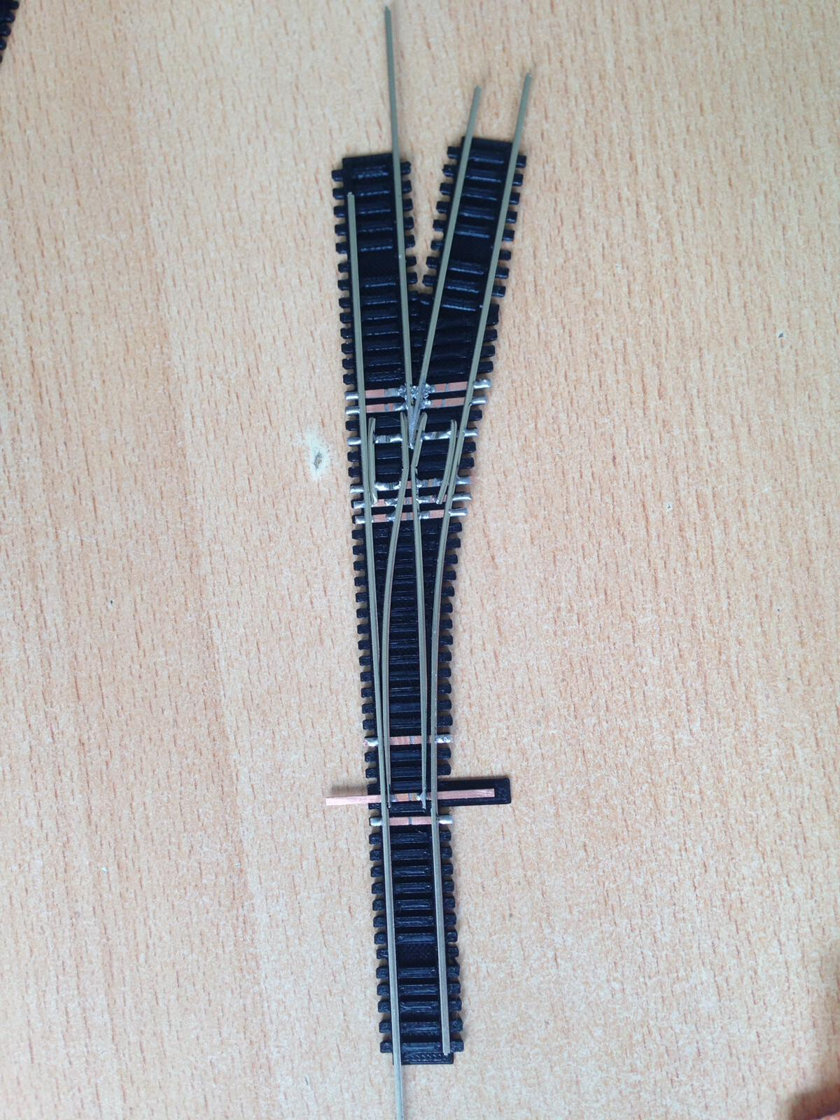
Question: how are you attaching the rails to the printed ties?
1 Like
Thanks! Pliobond 10 Inch Curved Tracks Handlaid On 3D Printed Track Jigs & 3D Printed Sleeper Ties For N Scale Trains - YouTube contact cement, plus the copper cross ties fit into the gaps and the rails in the channels - so it is many faces. It is the faces between the ties after using the x15 move function on the single tie component. I always manually erased the inner faces so far. Much worse on a curve.
If you use the correct modeling work flow/order of steps, you can avoid all that manual erasure.
Love to learn how! If you have any links for tutorial or videos would appreciate it! I need to rotate copy for curves - makes horrific tiny faces between ties.
When I finish with my student I’ll see if I can make an example for you.
Thanks! I start with a series of five ties and the gap as a component for straight things. But for curves it is a single tie that I rotate once for the copper ties in a jig and then I have to do a similar operation for the printed ties as a second build. So I end up with a couple dozen ties in an arc. Combining that is my nightmare… I also need to use the follow tool to add the groove for the rail base once the ties are all made… Groove gives a surface for glue to rail joint and holds the rail while the glue sets - seconds so it needs to be right real quick. As is I have to erase tons of pieces to do this now. I appreciate your help more than you will realize!
Solid Inspector2 only works on groups an components, because only groups and components can be considdered solid. Raw geometry can never be a solid.
1 Like
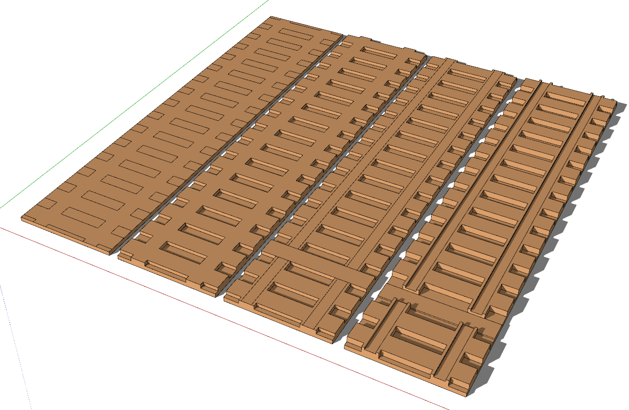
This is just a quickie for an example. If I have time later I’ll model a full turnout. Basic steps, draw the perimeter as a single face, layout the gaps for the spaces between the ties, copy the face representing the ties and the joiners between them, extrude that surface to make it 3D and create a group or component. It should be solid from the moment the group or component is created.

Obviously you can add other details as needed.
In a case like this, don’t model it as if you were starting with individual ties since that’s not what you will be doing in reality. Instead try to look at it more like the 3D printer will make it.
Thanks very much! I see what you mean for a different workflow. It looks like lots of small space push/pull since the ties have different heights on them - correct? At the split height I add a new face shape and continue pulling the faces. Such as where the tie ends are higher than the center sections. But better that than erasing a thousand faces! I will try to make a #6 turnout diverging rail back to straight section using your suggestions. The most recent thing I made for a #4 turnout - similar but another build… Returning a #4 Turnout Diverging Rail Back to Parallel With Handlaid Track And Not Using Flextrack - YouTube
In my quickie example the ties are all the same height but if you need different heights you should be able to work that out by adding edges and dividing the top surfaces as you go and using Push/Pull as needed. I suggested building the height like a 3D printer would and that should work for much of it but there may be time when it’s easier to push back down, instead. Here’s a simple example. The first three show building up to create details. In the last two I added some height before drawing the circles that became the raised bumps. In that step I was able to use a single Push/Pull step to lower the surface around the bumps.

I see in your video that you didn’t leave openings between the ties for your return to parallel track. To model that, I would start with the perimeter and give it the base thickness before outlining the ties. Then add the detail, pull up, add more detail and pull up or push down. Try to look for ways to push or pull the largest surfaces to minimize push/pull steps.
Cool stuff you’re doing. I’ll have to watch more of your videos. My son and I have an N-Scale Timesaver in progress. It’s been stalled for awhile, though. We used Kato track on 4 N-Trak modules. I’d like to reduce it to smaller turnouts so we can do a bit more on the modules. We’ve got the idea to add some buildings and other scenic stuff to sort of disguise the Timesaver and make it look like a small industrial area.
1 Like
Awesome information! I will let you know how it works shortly. If you are making a timesaver (yay!!) I highly suggest adding the Inglenook Wye as it is a simple and very prototypical set of sidings that add nicely to the shunting puzzle. It is
also nice math for the most number of cars on the siding that lets you still reach them all. Adding Inglenook Wye To Timesaver Shunting Puzzle N Scale Layout Design In SCARM Plus Wye Variations - YouTube These are the things that made me decide to start the train layout - plus endless lockdown in Amsterdam… Thanks very much Dave!!
1 Like
I like the idea of adding the Inglenook Wye. If I reduce the size of the turnouts I can probably get that in without making it too cramped. We started with the N-tack modules because our local hobby shop was getting a local club started. It didn’t take off but unfortunately. The modules are to have parallel tracks at specified spacing so we have those with a double crossover between and the time saver off the inside track.
By the way, your profile says you are using SketchUp 2017 Make. That would mean you haven’t got access to the Solid Tools but you might find Boolean operations to be very useful for what you are modeling. I would suggest having a look at Bool Tools 2. It’s an extension that provides Boolean tools which works in Sketchup Make as well as Pro. Not free but not terribly expensive and it’ll let you do some cool stuff faster and easier than doing it manually.
I’ll also make a suggestion. Check to see if your slicer will let you specify import units for the .stl files you are making if it will, do your modeling in SketchUp with Units set to Meters. If you are normally modeling in inches you’ll just enter the inches as meters. Export the .stl that way. Don’t scale the model down. Then import into the slicer using Inches as the units. As an example, the body of this little machinist’s jack is supposed to be 56 mm tall. The knurling and the screw threads would have been problematic if I’d modeled it at that size so I modeled it 56 meters tall.

Here’s the resulting .stl uploaded to i.materialise for printing using millimeters as the import units.
