I am trying to show only linework for complex furniture 3d furniture and cannot achieve consistent outlines with profiles turned on in styles… can anyone explain exactly how SU determines which outlines it will display in a 3d model…
eg… if I have a sofa,
is only the primary outline shown?,
only the outline of curved surfaces ?
How are groups or components outlines in the primary object show?
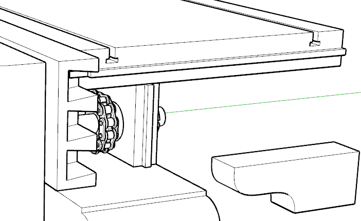
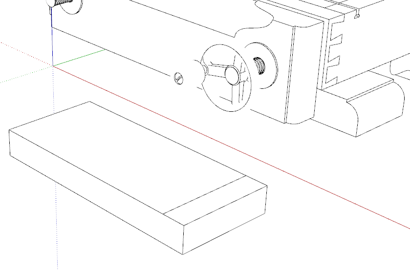
It’s pretty simple. Profiles are shown when only one face that the edge bounds is visible. Profiles are applied by component or group. In the above it is pretty easy to see how this works. The front jaw of the vise shows profiles around its perimeter and in a couple of spots on the lamb’s tongue above the hand wheel where the adjoining faces are not visible. Profiles are also shown around the dovetails because the front and side are two different components and the faces in the sockets between the pins are not visible.
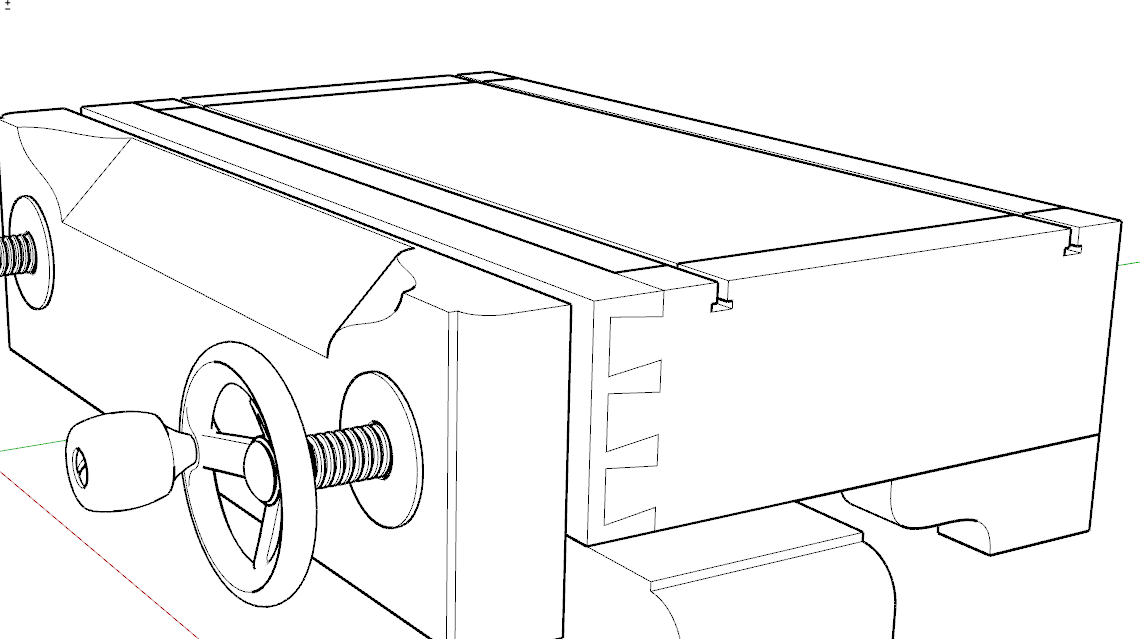
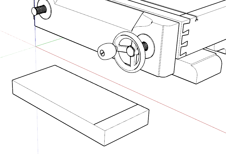
Below I exploded the two dovetailed components and made a single one. The dovetails are now outlined as non-profile edges because the faces on either side of the dovetail outline are visible.
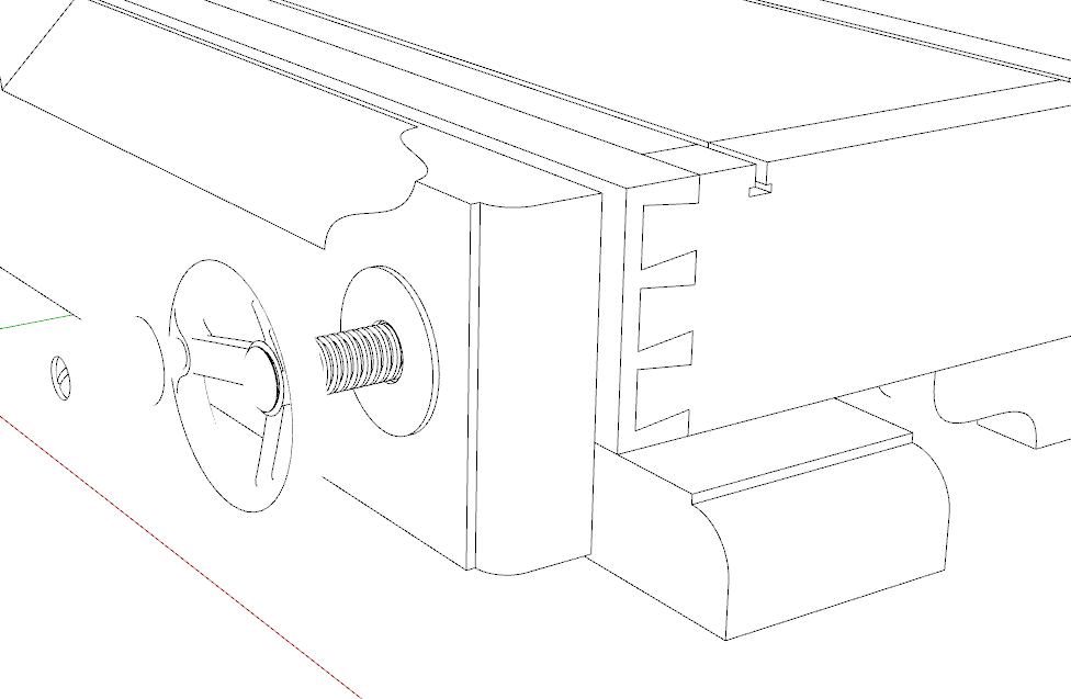
It’s also worth considering that if Profiles are turned off, softened and hidden edges are not shown even when the adjoining faces is not visible. Notice how the outline of the knob, wheel and some other spots disappear without profiles.
Thanks Dave for that very clear description… was that by your own trial and error or is there some official description somewhere…
Unlike your mastery of the process I was getting results like your 4th image… maybe it it was because the sofa had many hidden edges or it might also be video driver issues … I will re investigate know you have explained whats going on with clarity…
I guess I’ve never seen any “official” explanation of Profiles. I learned this stuff a long time ago as I was playing with styles to set up one for my default templates as well as for image exports.
If your images are like like my 4th one, I would expect that the style you are using has Profiles turned off. The default Hidden Line is set up that way as are the others that are shown as “fast” styles by the addition of the green stopwatch icon.
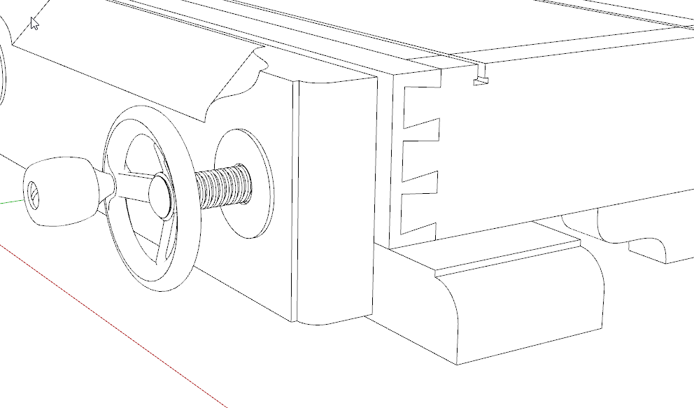
Personally I prefer the working style to include profiles but with them set to 1 as in the last image in my previous post.
I did miss out another case in which Profiles are displayed. That is when a line drawn on a face doesn’t divide that face. That can be leveraged for display in some cases but it’s really a good trouble shooting tool. The line drawn across the top of the box in the foreground doesn’t go all the way across. The gap isn’t easily seen but if you were to try using something like Push/Pull on one side of the line, it would move the entire face of the box.
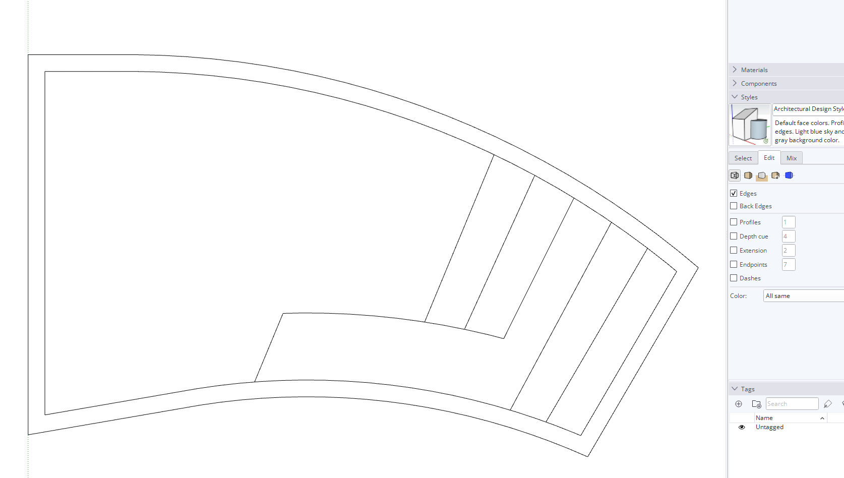
@DaveR so I’m having a similar line weight display issue.
I understand “why” profiles are displayed in different weights, my issue is they are totally random in this plan view.
When I group a single surface plane, which then invokes the thicker profile, all good.
However, when I explode the same surface group the varying profile width line will now display in a different area. This is only in Top Plan view…when viewed in 3D, orbit etc…the profile lines are as expected,
Secondly…
Then when viewed in Layout, there is no varying profile lines, all lines are displayed according to the chosen line scale modifier. Is this normal for Layout to ignore the different profile surfaces, whereas Sketchup will display them?
This is a case of the graphics card being confused by the stacked edges of the 3D model. You could turn Profiles off or set them to 1 in the style. Then all of the edges would be displayed the same.
This seems unusual behavior of the graphics card, due to the basic nature of the simple model, low number of polyline in the edges and it being basically an on axis push-pull extrude of the step…
I created a simple set of steps in the same file, and not issue there displaying the stacked edges.
Turning the profiles to 1 does help, but then we loose the graphic nature of the SketchUp model and the different profile line weights we have come to love.
In regards to Layout being able to display the edge profile…YES…did you stack the inner pool shape on top of the outer profile shape?
How did you create the two line weights in Layout?
I did stack a couple of viewports showing the same scene. The one on the bottom has the Line scale set to 2 and rendered as Vector, the top one is set to .5 and rendered as Hybrid so the faces would mask the unneeded edges underneath.
It may be that the Profile edges should appear more consistently in the model but until it is fixed (if it’s something that can be fixed) this is a simple way to get that appearance.
FWIW, I would suggest turning off Length Snapping in your SketchUp template. Nothing to do with this graphics thing but it will impact model precision.
If I interpret the screenshots right, all the lines should be displayed as profile edges so there being no differences in line weight shouldn’t come as a surprise. Edges would be shown as thin lines only when both the faces they are attached to are visible, so a step viewed from above is always a “profile”.
Edit: Responded first viewing only the screenshots. Looking at the model, it is slightly glitchy, probably because Length Snapping is on. The steps that should be vertical aren’t quite so the display gets confused. I switched the units to Millimeters to get more decimals:
I had always assumed Length Snapping was tied to, and required for “inferencing” and now after further reading other threads I see it isn’t. Then the whole debate about why length snapping is default on came to light…Consider it now and for further more turned off in my templates.
@Anssi, I now see the issue with the steps being off, though when I drew them they were created on the surface plane of the ground of the pool then “push/pull” up to create the riser and subsequent stair tread. Is it safe to assume that with length snapping on, this led to the slight difference in the vertical axis? I always thought push/pull only worked exactly on any of the three global axis?
if you draw a rectangle in top view it will be flat on the groundplane. You can draw on that rectangle watching for the “on face” inference.
The same for front view and left or right view…
Of course you can delete the big rectangle after you drew your shape.
If I orbit around your latest model, I see profiles come and go on numerous edges depending on direction of view. I checked the positions of vertices with the text tool, and they all agree to within the max decimal places of the display. That suggests to me that the issue arises from limited precision in the calculations the graphics engine uses to decide which edges to highlight as profiles. If I am right, there is nothing you can do other than to enter it as a feature request to add a tolerance to the test used internally.
The version you most recently uploaded appears square to me, the nodes I queried in the steps look squarely vertical over each other. Where are you seeing inconsistencies in this model?
If you suspect your starting plane is not flat (in this instance I believe it is flat) you can fix it by rotating in a given plane X or Y (arrow keys will lock the plane of rotation) and looking for the on axis inference, for very small angles you sometimes need to rotate away from an axis by a significant amount and then rotate back to get the inference to trigger. Do this for X and Y independently. Or you can run an extension like Enroths Flatten to Plane, however this will make a flat “projection” of your geometry onto the ground plane which will necessarily distort the bounding edges of the geometry. Rotating manually is more precise but I don’t see that it is called for in this model.
I created the model again and made sure the starting plane was flat using Enroths Flatten to Plane as suggested. Yes, the projection is accurate enough for this conceptual modeling. Then while in plan view, I made sure to inference all my stair edges to the inside edge profile of the pool wall.
Then I offset the inside wall 5" to create the top lip surface.
Next, I push/pull all the risers and pool wall up. So it has to be perpendicular to the ground plane X,Y.
It still produced the same varying display of profile edges and thickness when viewed in Plan view, as shown HERE & HERE in attached image.
Oh well…
Therefore one must assume it is a graphics engine calculation issue as @Slbaumgartner suggested in the post above yours.