
this is what i’m working on lately, and i wanna make this move what i like, but i make a move in one axis than other goes not a right angle and hard to make a move where i want to. So this is what i ask for “Can I put ‘Q’ tool in group of model so if I click one of that and press Q than it apears in location I Designate?”
I sincerelly didn’t fully understand, sorry, but I guess you want to move along an axis. You can do it:
- If you hit M for move;
- And then get your cursor close to an edge until “on edge” is displayed;
- And you hold hold down shift key on that edge (don’t let go);
- You can now press anywhere on viewport as a reference point;
- And anywhere on viewport again as the landing point for the reference point.


you may find it easier if you Turn OFF Textures and Turn ON Xray mode and Hidden Edges…
john
- Click and hold with your “Q” tool on the centerpoint you wish;
- Don’t let go mouse;
- Drag the mouse and an axis of rotation gets generated;
- Let go the mouse and you start rotating around that axis;
- You can either hit a reference point and landing point or a reference point and an angle;
- You can use the axis along the reference lines you have in your components and get the job done:

thx for answer. it seems that is easist way so far, but i want it more convenient way. so i’m gonna suggest fuction to developer.
ye, that’s the way i use it now. can u see the lines out of objects? that’s guide line i made. way i want to suggest to developers, put protractor in group and when i click it than press Q i can see it and move objects without select location…
man…i hope my meaning go right…
Click on THIS LINK to see a different way of moving, rotating groups or components…
there are others around as well…
john
So, you want to select an axis of rotation without having to set the 2 points.
How would you propose this to happen, by selecting an edge, or using group’s axis or some other way?
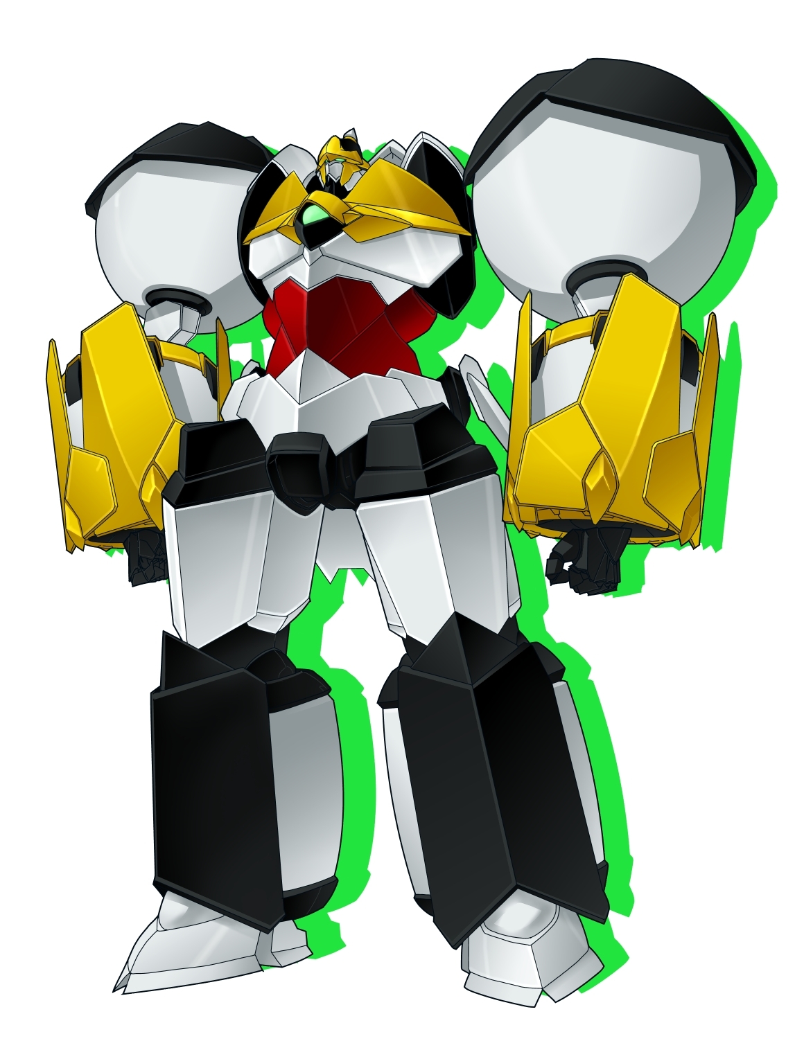
Can you give additional depth of info on what you are dealing with. Based on my back ground I come to conclusion what I am seeing as a possible multiple gimbal space craft design. As such the conservation of momentum will apply and when you move the one component the whole space craft will change position.
Component definitions are in variant when moved, rotated, scaled, translated so you can perform that about any axis you want without affecting a different instance of same entity in your model not with standing the possible kinematic issues per above.
Posting skp models is preferred vs such pics.
that’s good! But i have little problem for that which is My SKP has no plug in tab…may be mine is trial version?
You will have the plugin tab once you activate a plugin even if you have only the free ( make) version. Go to windows, preferences, select extension and then select appropriate box;
After seeing some of the model I now have further questions / suggestions.
Sorry for them but trying to give you some ideas:
I thought in your first post there are two gimbals ( I guess we should say joints) with one axis for “elevation and other " azimuth”… You have been shown above how to set one axis of rotation. However you must also address collisions of other geometry in your model; It may be better if you look at ball and socket to give more degrees of freedom of movement. For example the biomechanics of an elbow joint is 0 to 140degs in flexion,80 degs of pronation and 90 dges of supinations.
I under stand you are not trying to duplicate a real joint just some ideas for you. FYI I think the Barbie doll joints are patented.
