Can anyone help me cut the screw in this file in half? I can not for the life of me figure out how to do it. I just want it to be about half as tall, but I can’t scale it down because I don’t want to mess up the threads.
Phone Cord J Hook W_Screw.skp (1.0 MB)
I didnt try softening the edges, but i did try the rest and i just couldnt get it. But thank you anyway.
The tricky part here is deleting all the parts you don’t need. Since there are a lot of little faces it will take some patience. There is a very powerful tool for doing this called trim, but it is limited to subscribers. Modeling Complex 3D Shapes with the Solid Tools | SketchUp Help
Paul’s point is good regarding Solid Tools however you’d also have to make the screw component a colid and it isn’t yet.
Where did you get this? I presume it was originally a .stl file. Can you share that file?
One thing that would help is to work at a larger scale. I’d probably use the Dave Method for that to avoid tiny faces and the issues they cause.
As for deleting the unneeded part of the screw, you can switch to Parallel Projection and one of the standard views. Then use a right to left selection window above the cutting plane to select most of the waste before pressing Delete.
Is the screw supposed to be some standard size?
Well, I was trying to design this for phone cords from scratch. I figured out how to make a screw, but I couldn’t figure out how to make the threading inside the clamp. So I chopped the threaded part and took the screw from this file, scaled it to size and used it. Here is the file.
Unnamed-Headset Holder with cable v2.stl (1.7 MB)
It’s too bad you’re working with the free web version. You’d have an easier time with SketchUp Go or even SketchUP Pro.
Again, does the screw have to match a standard screw?
Once you have the external threads modeled correctly you could use them with the Solid Tools to create the internal threads. They won’t be exactly right for internal threads but they’d likely work for 3D printing.
The screw in your file needs some help to be 3D printable before you even consider reducing the length.
Nah, it doesnt have to match a standard screw. Also, im new to 3d modeling, so i dont even know what solid tools are. Also, the screw and threads in the file work perfectly fine. Ive already printed it once. Thats why i know i want it shorter. Lol

1 Like
I watched that one already, but it did not work for me.
Saying something didn’t work for you isn’t very useful for trying to help you.
Why didn’t it work for you?
At what point did it fail?
What part of it don’t you understand?
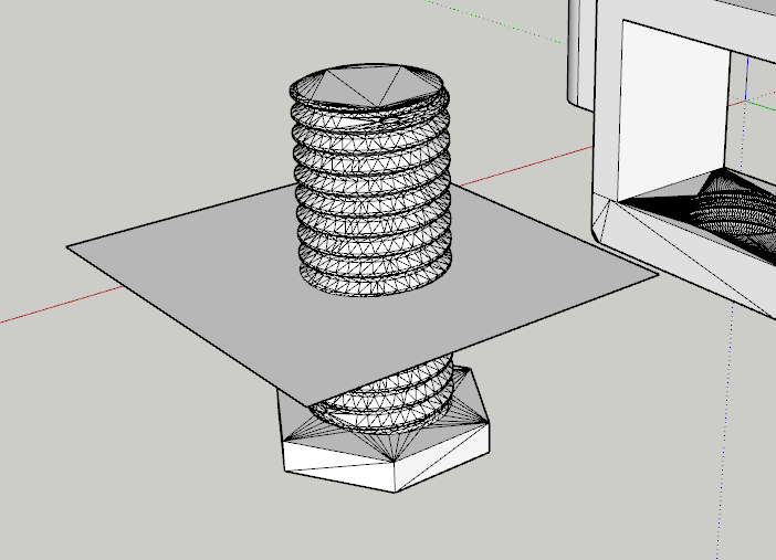
For example here is your original model cut in half in the web version using nothing more than what has already been explained or shown to you.
What part of this doesn’t work for you?

Thanks Box. I was thinking. " Hmm… What do they mean? it’s not hard erase to the excess once you see how." Nice video.
Only one of the objects you’re intersecting can be a group or component? Is that correct?
@cakrupp Both can be groups / components if you want. What happens is the edges of the intersections are placed in the current context. So either you are INSIDE one of the groups when you make the intersection, or you are outside both (in which case the edges created will not be interacting with the faces or edges of either group). So it depends on your method and what the results need to be.
Only un-grouped geometry, within the current context, will directly give get you the faces representing the cut-out surfaces combined with the remaining faces of both objects. What is normally done then, is to erase the geometry of the object you don’t want anymore (the excess).
Thanks, so if I want the intersection edges in both groups, does it work with just one as a group and the other raw geometry. It seems that’s what I’ve been doing and it has worked as stated. (I think…)???
I’m confused. You are talking about two groups and then one group and the other raw geometry. And in what way is it working for you? The tool will create edges in any case where intersections are to be found. Where these edges end up gives different results. They will divide a face if the present context has a raw geometry face to divide. They won’t divide a face that is “protected” inside a group when performing the command.
There are some Square One and Skillbuilder videos on this.
This all depends on two things:
- What is open for editing at the time you do the intersection (the model, a group, a component - called the “context”). The new edges created by intersect will be added to whatever is open regardless of what faces were used to make the intersection.
- Which Intersect Faces option you choose. “With model” will create intersections with everything in the model. “With context” will create intersections among the faces of the open group or component instance and put them in that group or component instance. “With selection” will create intersections among the faces of the current selection (which will necessarily all be in the same context because you can’t select things from different contexts at the same time) and put them in the open group or component.
So, you always have to either expect the new edges to be loose in the model or else open a group or component for edit before doing the intersection.