SketchUp Pro 22.0.353 on iMac running Big Sur 11.7.
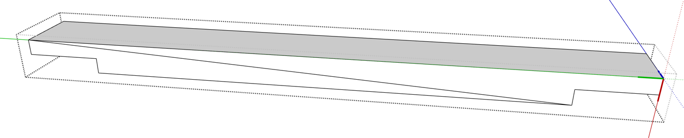
I’m creating a rack for my wood pieces and ran into a problem I can’t seem to resolve. I’m trying to edit one of the components, a simple piece with two lap joint cuts at each end.
But here’s the kicker. Now when I draw the diagonal line to re-establish the face I only get a partial face, as if that face is no longer flat. Say what??
I used the the same process (without deleting the faces step) on other components and did not have this issue. What am I missing?
Here’s my file for reference. lumber rack.skp (135.4 KB)
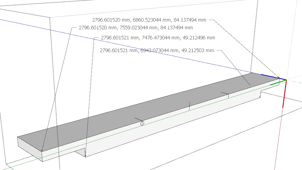
Looking at the component axes in a number of your components and some of the other details it seems to me you are working harder than you need to and could easily be inducing tiny errors in your model that could lead to things like you are seeing.
tweenulzeven,
Yeah there is more to the story but I wanted to keep the question simple. The rest of the story is:
In the shelf structure I need to show cutouts for laying in the round cross pieces (1/2" EMT). I was able to do the cutouts on the side components of each shelf as you can see on the .skp file but not on the end and center components. I guess one SketchUp axis is happy but not the other. So…to make the cutouts I draw a 3/8" line on the edge face in each of the three locations, then I draw a 3/4" circle so it is tangent to the top surface, draw lines for the sides, delete extra lines and then do a push/pull to create the depth of the cutout. As I said, it worked fine for the components in one axis but not in the other. When I draw the circle, it is not appearing as a flat circle on the edge face of the component even though all the axis and measurements seem to indicate no extraneous deviations (i.e. everything is orthogonal).
Dave,
To answer your first comment, I can almost guarantee I’m working harder than I need to, that’s the inefficiency I suffer from being an occasional user rather than a hard-core SketchUp master
One reason some, if not all, of my components are off-axis is that I had to tweak component sizes to conform to the actual boards as they came off my saw/planer. And I am trying to set up the design so the 1/2" EMT “grid” pieces are one length and can fit either way on a given shelf (i.e. configurable grid).
I see your point about the X values and that is very interesting because after my initial frustration with the noted issue, I deleted all edges and surfaces of the component and then redrew it, making sure to say on axis. I created the face and then pushed it to get the desired 3 1/4" width. Is there a better, more robust/acceptable way to draw this component?
You mentioned that when you look at it there is no missing faces or triangulation. Did you repeat the steps I detailed in my opening post?
No. I thought you were uploading the file with the missing face. It doesn’t matter though. The discrepancy in the corner locations makes it clear why you are having the problem.
Might be worth learning some simple, basic methods to make your work flow less hard. I’m reworking your shelf to give you some ideas in that vein.
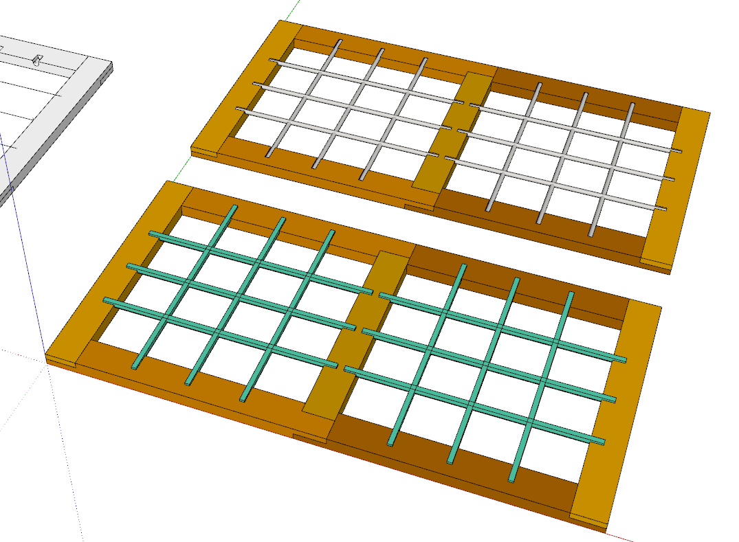
Let’s see if this helps. I haven’t added the notches for the vertical pieces yet but that’s trivial. I’ve added colors so you can see which components are copies. I started typing out a description of what I did but it was getting too long. Maybe I’ll record a video instead. Screenshots are below.
Note that I used Eneroth Solid Tools to create most of the joinery. This is quick and precise. The key thing about the modeling process is thinking ahead to what will come so you can be efficient and not induce errors.
Dave,
Thanks for taking the time to “school” me in some of the features of SketchUp that likely would have made my design go a lot faster/smoother. Believe it or not but I have (do) use most of the combo tricks you showed in the video but I have not used the Trim feature so that’s one I should try.
The design process for my wood rack was iterative. I started with a raw concept, some “scraps” of lumber and a couple changes in direction along the way so the process of capturing it in SketchUp was not a serial design then build process. I started with a rough design idea, then cut some rough lumber pieces, refined the drawing, machine the cut pieces to general size, refined the drawing again (that’s where I’m at now), and then I’ll finally cut and assemble.
With your guidance and more perseverance I worked out the issue I posted. Just a little more work on the base frame, so it can use the same length EMT cross pieces as the other “shelves”, and then I’m into the final stage of creating cut sheets for the material. If I remember I’ll post a picture when it’s all done, if anybody cares.
Again, as always thanks for your help.
P.S. What’s in the casserole?
Update 2/4/2023
I mentioned I’d post a picture when it’s all done. Well, it’s all done and ready to configure for loading. Note the notches in each “shelf” section provide for the 1/2" electrical metallic tubing (EMT) to be inserted either direction depending on whether the items (boards) are to be stored lengthwise or straight in. The tubes will in fact rotate so as to provide a kind of roller action as items are inserted or removed but that’s just a side benefit.