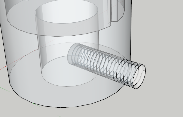
I am currently making a cylindrical fixture to spin a stub on a driveshaft and I need to put an M6x1.0 thread through the cylinder as a set screw. I use EP Fasteners and Holes to make the thread but how do I put it through the cylinder correctly? I am able to make the hole through there and intersect faces but not sure about how to do it so the threads are curved with the OD of the fixture. Here is a look.
Run the threads out past the surface of the cylinder, use Intersect Faces with… to generate the edges where they cross, then erase the part outside the cylinder. Depending on how you have used Groups or Components, you may need to be careful to open the right one for edit and possibly copy+paste-in-place to get all the bits into the same context. Also, you will very likely need to use the The Dave Method to avoid problems with loss of small faces where the threads cross the cylinder.
Yep, this is what I do as well.

Can you upload the two components - cylinder and thread - to try it here? And if you make the thread longer, it will be easier to trim off the excess.
Are you scaling up (as in the Dave method? If just working full size, the faces will be too small for SU to work with, and they may get merged or fail to form.
You aren’t putting the geometry of the screw inside the tube component/group so of course it’s not going to separate the surfaces.
Dave,
Can you please explain a little more? Are you saying I should have put the threads in the cylinder and then added everything to a component? Forgive my newbieness, and thanks for the help.M Driver1.skp (773.0 KB)
Not exactly. The edges and faces of the threads needs to be in the same context as the geometry of the cylinder. So move the thread component into position and explode it. Get rid of the hole in the cylinder first. Then use Intersect Faces to make the intersections between the sides of the cylinder and the thread geometry. Erase the skins over the hole inside and out as well as the bits of the threads extending inside and outside the cylinder walls.
Make the whole thing a component, copying the component and scaling that up (using the “Dave Method” that was mentioned earlier) before doing the Intersect Faces operation will be helpful.
The end result is that the threads in the hole are the remains of the thread component. Since SketchUp is a surface modeler, you need to create that geometry for the threaded hole.


What is your plan for these threads? Are you intending to 3D print this thing and are you expecting usable threads?
You’d probably find all this easier if you were working with a longer thread component, too.

If you do want to use this as a 3D printed item, I would make a plain hole in the print, drill it out to the correct size, and tap it.
You can make (and I have made) a rather larger - 22mm- printed screw, which fit perfectly without fettling, into a manufactured 22mm threaded socket. That was with the screw vertical on the print bed.
But I wouldn’t expect it to work well for an internal thread at this much smaller size.
Agreed. Those threads from the extension would be pretty hard to use in reality.
I hate to say it but im still lost. I moved the threads into position and exploded them. I removed the circle face from the back end. then I selected both and intersected faces but anytime I select like you did in the gif, it selects the whole thing. What am I doing wrong here?
Did you explode the thread component?
Yes. I moved the threads into position, selected them and exploded them. This is even after I scaled them up 35. Then I removed the flat surface from the back end. Selected both and intersected faces with selection and it still doesn’t separate it.
35 what?
Upload the SKP file as you have it.
Ok I finally got it to work. How do I scale it back down accurately? I just clicked scale, grabbed the corner, and typed 35.
Use the inverse of the scale factor you used to scale it up. If you’d used “The Dave Method” as @slbaumgartner, @john_mcclenahan, and I had suggested, you would just simply close the enlarged copy of the component and delete it. Then Zoom Extents to return to the original copy.
Is there another thread program you use that would be better than this? I need to put an M6 thread at the bottom and 3 around the top to secure the insert.
If I was going to hope to make 3D printable threads that are usable, I’d draw them myself using the Helix tool in Curve Maker and Eneroth’s Upright Extruder. I still think you’d get better threads, though, if you cut them after the part is printed. Just draw a hole a little smaller than you need for tapping, maybe 4 mm diameter. Drill out the hole with a 5 mm drill and then tap it with the 6 mm tap.
If you are manufacturing it from metal, don’t bother drawing threads at all. You’re going to have to drill and tap it anyhow.
Ill be having this made out of metal but want to show in the model how it will look exactly
Well, then you can do what I suggested and draw them manually using the tools I indicated. I used them to draw these Acme threads. You just need to use the correct thread profile.
