Hi All. I’m trying to do something that seems simple, but it’s eluding me. I’m drawing a hollow cylinder (tube), and I will need to drill a hole through the side. Obviously you can’t just draw the circle and push it through the cylinder, since you can’t push/pull on a curved surface. I realize I can’t be the first to ask this, but I’ve not been able to find an answer. I must not be wording my searches correctly. Can anyone point me in the right direction?
Draw the circle for the “drill” away from the tube, not on the surface. Then it’ll be a single face you can push through. Select the geometry and use Intersect Faces to make the intersection then delete the drill and the skin over the hole.
1 Like

Wow! Not only helpful, but fast as well! Thanks guys! I’m a little embarrassed by how simple the solution looks, and how long I’ve been trying to figure it out myself to no avail.
Thanks again!
Understanding the underlying geometry of a curve helps too.
Curves are actually a bunch of flat faces masquerading as a curve.
Turn on hidden geometry and you can work between the lines as they are single faces.

4 Likes
I have the cylinder. The inside is a D hole. The thru hole goes thru D flat only - it is for a set screw.
I do all all that- create circle on outside of D flat

Push it thru cylinder
,

& reverse face of hole
.
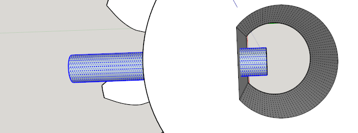
When I select the hole & cylinder
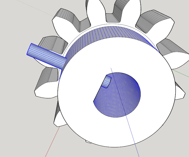
then intersect faces
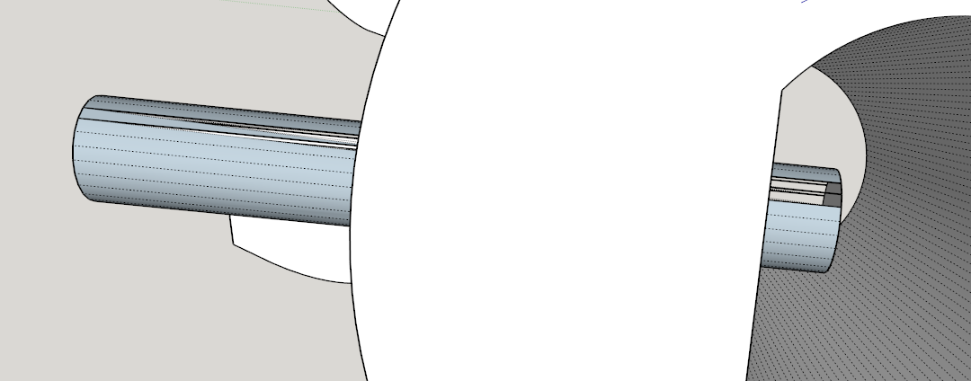
it breaks the hole shaft. Then when I delete the external hole part on the outside

it breaks the cylinder.
what am I doing wrong?
(SU2016)
Try the Intersect routine after scaling the model up by a factor of 10 or 100. You have a huge number of vertices on the curves and thus very tiny faces which will cause ou problems.
I was able to add a few lines and run it thru SuSolid and it fixed all issues. But what u r saying is that the hole should be located on segment faces and not curved faces.
No. I’m not saying that, specifically. the thing is, you’ve got small (narrow) faces to begin with and the intersection of the cylinder for the hole and the outside of the sprocket hub will create new endpoints that are so close together, SketchUp will consider them coincident. The result is the weird geometry and holes. By working at a larger scale, you can avoid the problem and get those faces to fill. Then scale down.
1 Like
What about if I want to have 12 holes in that same cylinder?
I have an issue after I create one hole it is not able to replicate in a circular array…
In that case, you’d need to array the intersecting cylinders and create 12 separate holes.
In cases like that it pays to think ahead and create an original gear wheel with a number of segments that can (hopefully) cope with both the number of teeth and the number of drill holes you intend to create…by having the number of segments that is a common multiple of both.
That way, you should have identical configuration geometry right around the curve and be able to array the holes, or anything else.
1 Like
I hope no one minds me resurrecting an old discussion, but this is what I found trying to research my problem. It looks like a good place to start from.
I’m trying to intersect one cylinder with another cylinder to form a tee pipe connection.
- Following the example here, I draw the first hollow vertical cylinder (OD=3, ID=2.25, H-4.625).
- Then I draw the offset circle for the drill but remove some of the center so it’s a ring, not a disc (OD=3, ID=2.125, Offset=.75).
- I push/pull that ring into the first cylinder, stopping halfway through. That creates a second hollow horizontal cylinder (Length=2.25).
- I select the outside and inside faces of the horizontal cylinder and Reverse Faces.
- I select the outside and inside faces of BOTH cylinders and Intersect Faces With Selection.
- Working through the open end of the horizontal cylinder, I can erase the outer and inner faces of the vertical cylinder.
- Working through the open ernd of the vertical cylinder, I can erase the outer and inner faces of the horizontal cylinder.
That works only as long as the ID of the horizontal cylinder (tested up to 2.125) is less than the ID of the vertical cylinder (2.25). I need both cylinders to have the same OD (3) and ID (2.25). When I make the IDs the same (2.25), I can erase the outer face of the vertical cylinder (step 6 above) but when I select the inner face to erase it, I’m selecting the entire inner face of the vertical cylinder. I can complete step 7 as well, but I cannot cut the hole in the inner face of the vertical cylinder. The problem must be related to the intersection of the faces but after many hours over the last two days, I can’t figure it out.
How do I do this, please?
SU Make 2017
Is this what you want to achieve?
I’m guessing you are talking inches?

It would be best if you attach your model so when can see what is going wrong.
My guess is you are running into a tiny face issue that could be resolved by working at a larger scale.
In future you would be better off starting a new thread for something like this rather than burying it in a 6 year old thread.
Thanks, Box. Of course, in the light of day, everything works better this morning. I started over to create a nice clean model to attach and I am now able to delete the faces I couldn’t yesterday.
2 Tee.skp (157.7 KB)
So as I mentioned, I Push/Pull the ring’s face into the cylinder half way (2.25"). From the outside, this is what I’m trying to accomplish:

Then I select the outside and inside of the horizontal cylinder, Reverse Faces, Select the inside and outside of both cylinders and Intersect Faces With Selection. That lets me delete the faces I need to to get to the tee shape. I have to reverse the faces of the new cylinder again to clean it up:

I have no clue what I was doing differently yesterday but I almost wore out Ctrl-Z trying to get this to work. It’s not quite as tidy as yours, but at least I have a usable model now. I guess there’s no way to remove those lines where the cylinders meet so the end result looks more like my first picture?
Thank you for looking at this. I guess if I’d have tried the 79th time, I would have gotten it without posting here. ![]()
Since Box is likely napping, I offer one tip.
If you turn on hidden geometry you can see the segments don’t line up from one part to the other.

So, if you rotate the horizontal portion with vertical, you’ll have a much tidier model.
Of course drawing it this way from the start would be best.

1 Like
Thank you, Shep. I have to remind myself to always draw circles with the radius along an axis. When I do that, the intersection lines are much smoother.

But when I delete the lines, I’m also deleting the adjoining faces. I’m not seeing the lines in your model.
The second image is before intersecting. The edge in the crease has to be there. It can be hidden using the eraser + ctrl
Ctrl-erase. I’ll add that to my notes for making a tee. I learn something new each time I use the program or ask a question. Thanks again.
Thank you very much. I didn’t know it was this easy. I’ve been trying for hours for the hole.
See this SU file for ideas.
Tee 4 inches.skp (255.5 KB)
It took me 10 seconds to get that using The Engineering Toolbox plugin.
To get a cleaner model, I can do an intersection and delete inneer walls that are not needed.