Here I have used the cardinal points, to resize the two circles, to the correct size if you want the thickness uniform, you could simply scale the whole circle if you don’t mind it getting slightly thinner.
Then I lock to the red axis with the right arrow to align it with the other ring.
2 Likes
Thanks.
If the thickness of 5 mm is to be constant for all this piece, then using a plugin like Joint Push Pull might be a good solution.
1 Like
You’d need to be careful using JPP for a shape like this, done incorrectly and the top and bottom may not be flat.
1 Like
Any advice? This objejt will then go through a object to creat a hole…
At the end it will be something like
Except
Will try it thanks
There are threads here and at sketchucation about creating a Volute.
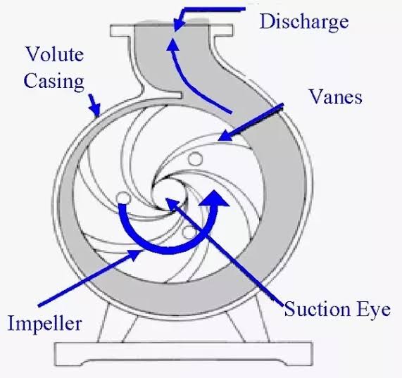
I recognize a centrifugal pump.
1 Like
Similar yes
That only works on the cardinal points of the circle, all other points will only move the circle…
Thanks.
Hey guys, i hate doing this. Im struggling my ass of.
After hours doing all that was explained and doing it successfully i can’t seem to get it to fit together.
I started over from scratch playing around to what works when. Now im stuck.
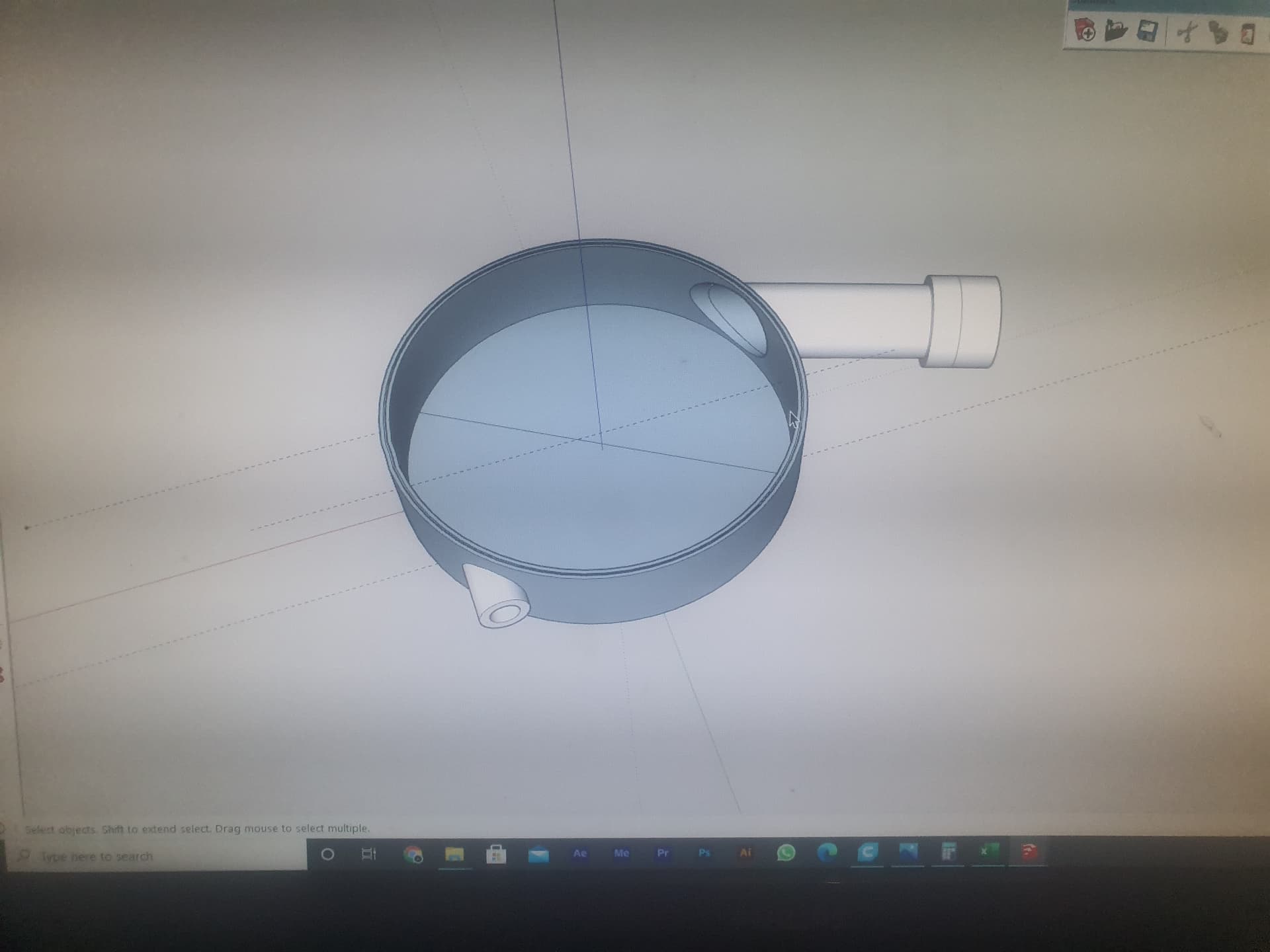
This is what i have so far.
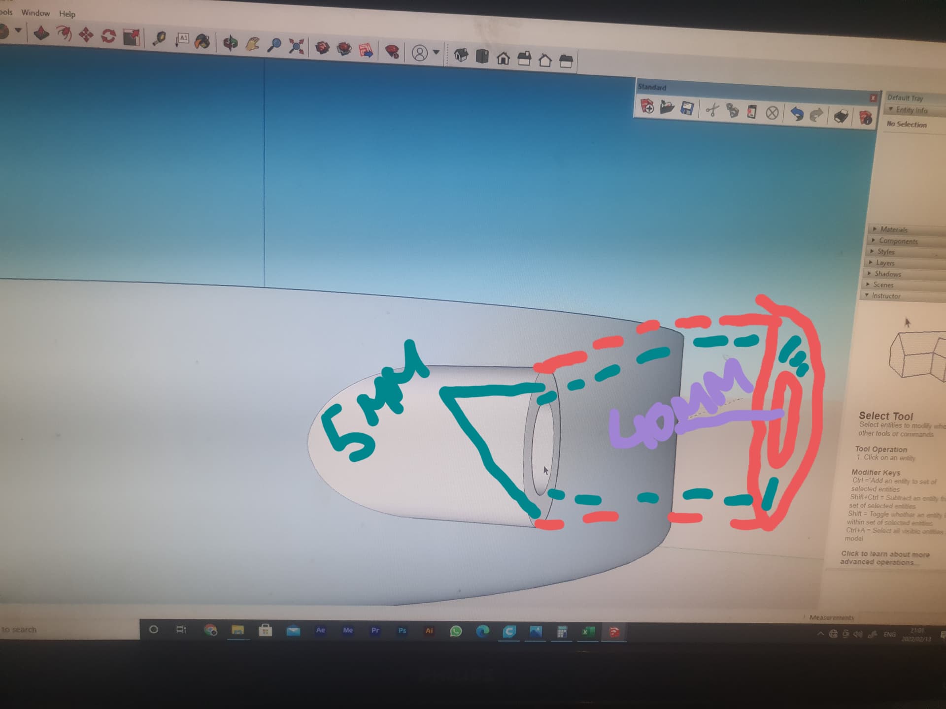
The “big bowl” (impeller will fit in here) is 46mm high with an offset of 5mm(made with the follow me tool)
Then you have the inlead. Inside the “bowl” the whole is 1515mm in diameter, going outside it it has an offset of 5mm
Note the 5mm offset im using is for when i print it my walls will hopefully be 5mm thick…
Thos inlead should look like the hand drawing i made wich you giys helped alot with.
So basically the whole in the “bowl” is 15mm in diameter, outside it must build to a diameter of 40mm.as per the drawn picture above.
The outlead , the hole through the “bowl” is 40mm in diameter, outside its 40 with a offset of 5mm.
Ill post another pic. With what i need to do.
Thanks
Sorry, I cannot make sense of your description. Do you have a picture of what you are trying to draw? Or is the design only in your head…
How about uploading the .skp file?
One thing to note from your photos of your computer screen is that the faces of the housing are reversed. They should be the same whitish color of the rest of the model.

test .skp (1.6 MB)
Thanks. Your help will be much appreciated, i do not expect you to do the work for me ![]()
Im not sure what you mean is reversed as i did it with follow me(it does change white and then blue) , you will notice on top i have a 1mmx,5mmx1mm step for a o-ring. I still need to make the lid
I’m intending that you’ll do your own work. ![]() Hopefully there’ll be some help.
Hopefully there’ll be some help.
The faces of the impeller housing are reversed. They should have the white front sides out. Sometimes the Follow Me operation will result in reversed faces. It has to do with the orientation of the profile face and the direction the path was drawn. It’s not a big deal if you fix it right away but it needs to be fixed. In the case of 3D printing, the faces in the model are the interface between air and print media with the print media being on the blue side. If you get reversed faces after dunning Follow Me or any other operation you should immediately correct them. Select all of the housing geometry, right click on it, choose Reverse Faces from the Context menu.
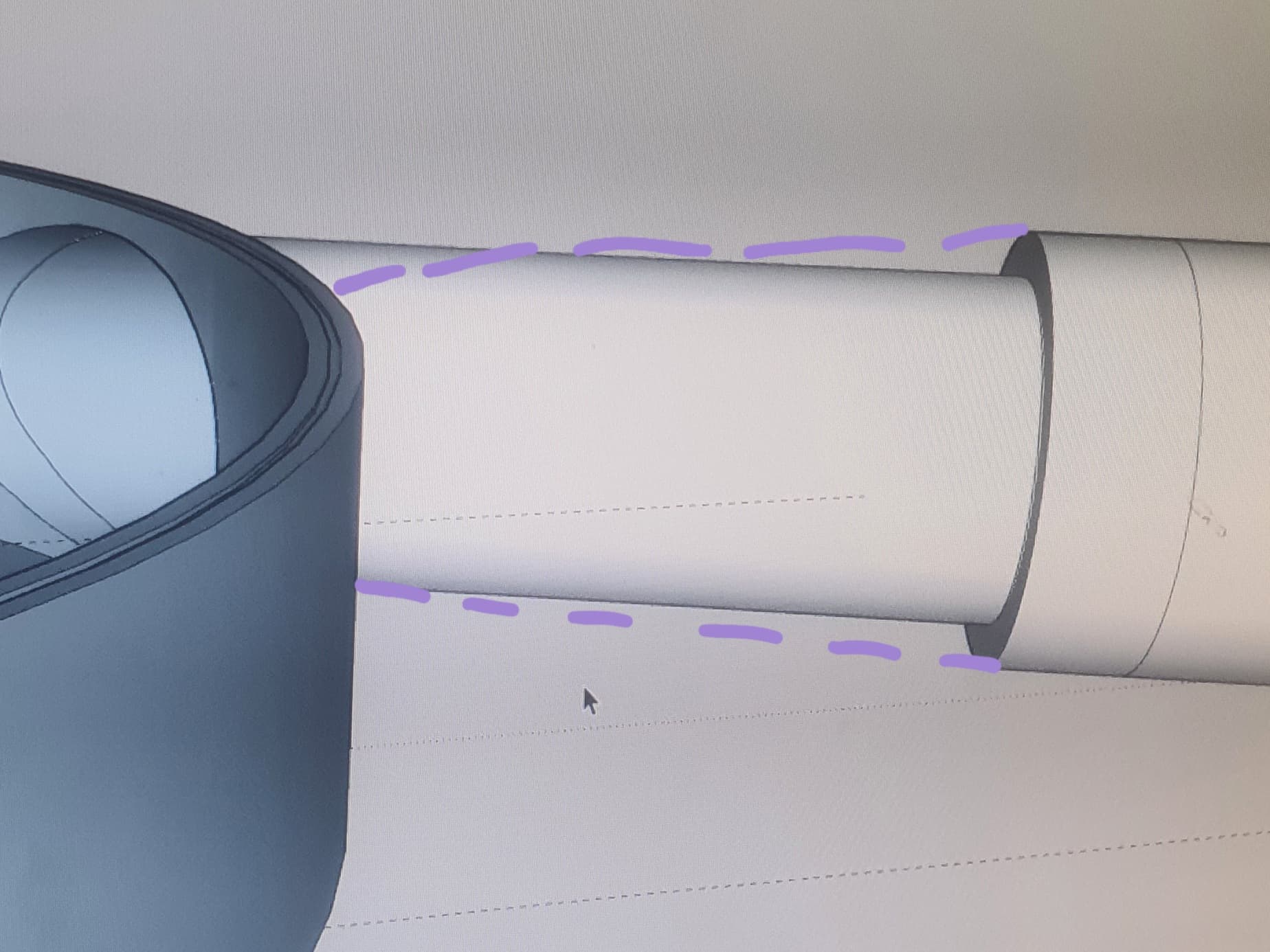
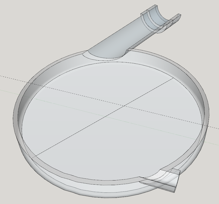
It’s still not entirely clear to me what it is you want nor the exact dimensions so I took a stab. I’m also not sure which is supposed to be the inlet and which is the outlet. Here is a section/X-ray view of your model. In your model the longer port has no thickness over most of its length. There are also internal faces where the short port meets the outside surface of the housing. There’s an internal face in the large part of the distal end of the long port.
I drew what I think you are trying to accomplish. Section view:
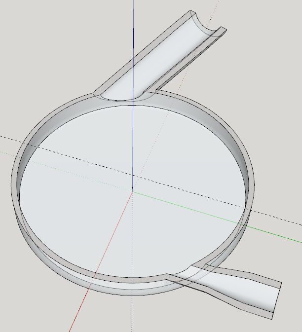
Note, no internal faces. The inlet and outlet both reduce in diameterwhere they enter the housing. The long one doesn’t have as dramatic a diamter change as the short one. I was just working with the dimensions I could glean from your model and your hand drawings but they might not be correct.
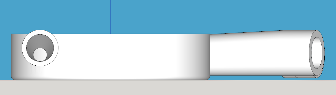
As you can see the inlet and outlet are offset so the tubes are offset upwards toward the cover side of the impeller housing.
Again, it’s probably not exactly what you want but maybe close?
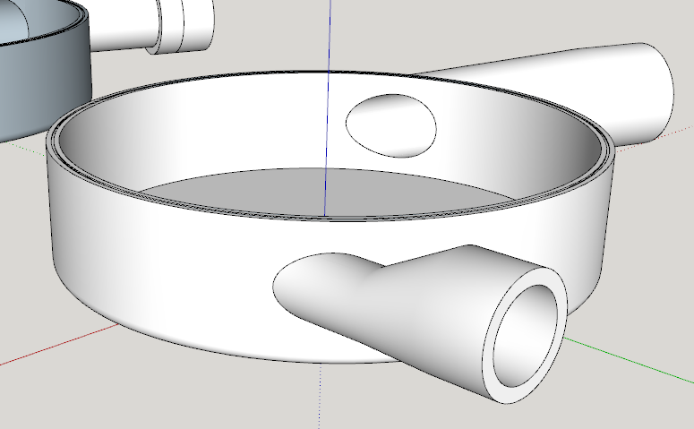
FWIW, in the modeling process I made use of the Solid Tools (Actually Bool Tools 2 because I used components and wanted to keep the results as components) to cut the ports to fit the outside of the housing, joint the ports to the housing, and “drill” the holes through the ports into the interior of the housing.
Trimming the short port to the housing. A copy to the left.

After joining the short port to the housing, I drilled the hole through with the cylinder shown to the left.
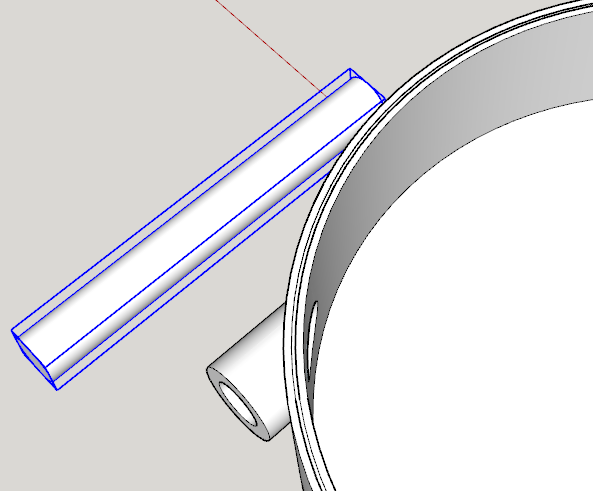
After that I added the length to the port and resized it before moving the end up as several of us showed you.
Personally I might change the shape of the short port to remove the hard edges and I wonder if there should be a fillet on the inside of the housing. I might also consider adding fillets at the bases of the inlets to avoid the sharp corners and stress risers where they meet the housing.
3 Likes
Thanks man, this at a quick view and read is exactly what i need. When i get home this afternoon ill have a closer look and try to recreate with your instructions.
Thanks again
1 Like