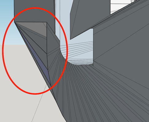
For some reason, I can’t delete holes in a face without deleting the face. What I circled in red is what I want to delete
dewalt cleaned.skp (230.4 KB) .
For some reason, I can’t delete holes in a face without deleting the face. What I circled in red is what I want to delete
dewalt cleaned.skp (230.4 KB) .
There’s a lot of hidden geometry (soften and hidden edges).
CleanUp3 gets rid of a lot of it but the ones it leaves are because faces aren’t coplanar and those edges are required to support the faces.
If you just want to fill the holes to make it solid, draw a line across each hole to form a face then delete that line. Then smooth the circle with option-erase (control-erase on Windows). That makes it solid, but it still won’t be flat which is why you have all those hidden lines going everywhere. Maybe it’s not meant to be flat and wouldn’t fit if it was flat?
Yes, I just want to fill the holes to make it solid.
How are you making the animation? I can’t see to do what I’m seeing–obviously I’m missing something.
So, I get a face over the circle by drawing the line. I then erase the line, and it looks good.
But, when I then delete the circle, Iose the face.
Can’t figure out what I’m not doing…
I didn’t delete the circle, I smoothed it with the erase tool holding down the option key. At the end I turned on “Show Hidden Geometry” to show that the lines around the circle were still there along with all the other lines on what looks like a flat surface but it is not flat.
Duh!
Yes, you said that, but I’ve never used the “smooth” erase. It worked!
Thanks!
It may not matter in this project but the faces created by all those softened/smoothed or hidden edges will probably be visible in the printed object.
Yes, there is a lot of non-coplanar geometry. I have a physical version in my hand.
There’s a good detail of detail that must be accurate dimension wise. It’s a battery dock, and the mating battery has to fit and snap lock.
At my skill level, that would be a LOT of design time and high risk of messing something up.\
But thanks for the reply!
I
This is my first time trying to do a design for 3d printing, so please continue to excuse my ignorance.
I’ve never worked with solids.
There are several battery dock designs on Thingiverse, so I went looking for one that were closer to being a solid without requiring faces to be closed, cleanup to be run, etc. But, it seems they all have the same issue.
I’m pretty sure the designs are “3d-printable”, so maybe it’s not necessary for them to be solids in Sketchup? I thought I needed a solid to do the modifications I want, but maybe that’s not so.
I was hoping to learn how to do this efficiently, since I can see wanting to do something similar for future projects.
I thought what I want to do was pretty simple–maybe even trivial. Change the dock mounting from screws to using a bracket that will exist to space a round pole from a square pole:
bracket with dock.skp (431.4 KB)
Basically, just add fillets and rounded edges to what’s in the attached Sketchup. Maybe “beef it up” around areas that look fragile And, add a place to mount a round push button switch…
Are these files all coming from an imported .stl file? If you tick the “merge coplanar edges” on import, it will make them easier to work with. Also choose metres as the unit to help avoid tiny faces disappearing. In the bracket with dock.skp file, it looks like you didn’t have that option ticked as there’s loads of coplanar edges that can be deleted without breaking the face. If you just created a cube, exported as STL then imported it back into SketchUp without ticking “merge coplanar edges” you’d have a triangulated cube in SketchUp.
It’ll be easier to work with a cleaner model. Even if your slicer software doesn’t mind, it will be much easier to remove a screw hole going through a simple flat surface instead of hundreds of almost co-planar triangles.
You might be having to work with someone else’s mistakes. There’s some internal faces in that latest file here:
A non-free but reasonably priced ($20) extension that might help is Vertex Tools. You could use it to flatten slightly off plane surfaces. It can do a lot more of course.
Here I used Vertex Tools on your original .skp file to flatten the top surface. I drew a line across each circle to form faces there and then deleted those lines. I double clicked in the face to select it and all its edges. I opened Vertex Tools and used the scale in z-axis widget. I moved it a bit then type zero and pressed return. This scaled them to all lie in same plane. Then I selected all those coplanar lines and used a plugin to remove them. CleanUp3 could do this too: Extensions → Cleanup3 → Merge Faces.
At the end I turn on hidden geometry to show that all those lines have gone from the top face and it is flat.
The first one I posted was actually a .skp before I downloaded. But, yes, the others downloaded were all .stl files. And no, I didn’t have the “merge coplanar faces” option checked on import.
Tried one with that optionn, and it DOES help. Thanks! But still much to fix. For example, 84 internal face options. That’s probably one you highlighted in the latest file.
I started modifying the design from the latest file. I was able to fix things up enough to extrude some flat sections on sides and start adding on from there. But, it sill has surface borders and internal face edges. Will Vertex Tools help with that?
Also, the short edges don’t go away, even when I scale up by 1000. That doesn’t make sense to me.
How would one go about fixing
I really don’t understand why, but when I “exploded” the modified design, all the short edges disappeared, and Solid Inspector was able to fix all the errors!
It’s good that it’s fixed, but I’m pretty clueless about why that fixed anything
Also, while Solid Inspector reports it as clean, SU Solid Tools disagrees–. When I select all and try to do an outer shell, it reports that something selected is not a solid.
Here’s the design I’m now referring to–Solid Inspector thinks it is clean:
dewalt extended.skp (144.5 KB)
SketchUp won’t let you create edges smaller than about 1/1000 inch. These short edges can exist in your model though. If you create large edges in a component, then shrink them down with the scale tool they’ll still be there. If you then explode that component, SketchUp will merge the vertices that are closer than the minimum and this can create holes in your mesh. It could also make short edges disappear.
The latest file, “dewalt extended.skp” was seen as solid here in Entity Info and Solid Inspector2. Sometimes they won’t agree though and the older version of Solid Inspector can help to find errors.
Here’s a close up view of tiny edges being removed with explode. There’s a face missing that’s 0.01mm wide and a short edge about 0.025mm long. The vertices that are close get merged and the short edge disappears. After exploding, it was made into a group, which was solid.
I was trying to break it so it made a hole but it’s been having the opposite effect so far.
Interesting…
So, while I now have a valid 3d object, some of the faces apparently had not quite coplanar vertices. I don’t why, since those faces were extruded from a rectangle I drew myself (the “plate” attached to the back of the dock).
I don’t have the right vocabulary, but those dashed lines on a face limited how far I could push back an orthogonal surface. So, I downloaded and installed vertex tools to get rid of them the way you suggested.
It worked!
I’ll have to spend the time to read the Vertex Tools manual.
I gotta say, it’s just “monkey see, monkey do” right now. I sure couldn’t tell that those faces aren’t coplanar, even when I zoom way. Just those dashed lines to indicate. And, don’t know what I did to make them appear. Maybe it happened during cleanup or the solid inspector “fix”.
Thanks again!
Ok, now I think I see what’s causing my most recent headaches
I turned on the style that colored edges axis and see the edges extruded rectangle I added are NOT parallel to any axis.
Don’t know how that happened. I’m going to start over and watch for issues more carefully every step of the way.
Inference points can be quite jittery when you have hidden components and complex surfaces in the background. It’s dead easy to click on the wrong point sometimes, or just jog the mouse ever so slightly while clicking the button. I’m much more careful than I used to be.


