Started with three DWG files (Right, Left and Front). Thought this was going to be easy, first impressions are often wrong. First had difficulty finding the right registration points. Still not sure I have the alignment correct. Started with right view, added thickness. Now, have no idea how to model the fillets and raised sections. Any advice would be greatly appreciated.
If you’re modeling it as a modeling exercise to develop your own modeling skills, I’m sure others will chime in.
But if you’re looking to model it because you need to add it to a project, Simpson Strong Tie has a LOT of their connectors in the 3D Warehouse - including this one:
I was unable to find the H1.81Z in the 3D Warehouse. The H1 was available, as you pointed out. The H1.81Z is the model for LVL and TJI material, the opening is 1 13/16" versus the 1 9/16" (H1). The dwg files for the H1.81Z were not available on the Simpson Strong-Tie site. I submitted a request and they added the files.
This exercise is more about how to develop a workflow for converting dwg/dxf files into SU models. I have imported the four dwg files (ISO, Right, Left and Front) into the included SU file. I need help in developing a methodology for aligning the views correctly. Also problematic is modeling the bend and reinforcement areas. Any help would be greatly appreciated.
Thanks, this is perfect. Is there a way to slow the speed of the video? Also, there is a small piece of geometry below the red axis, how/why was it created. You used Fredo’s PushPull extension, can this be done with native SU tools?
Since you have your profile hidden I can’t tell what OS or SU version you are using which makes it difficult to be specific.
Basically you should Weld those edges, in the later versions this is possible natively, earlier you need an extension.
Once welded use the Eraser tool with ctrl ,or option I think it is on mac, on the inner edge to soften it. And shift with the eraser on the outer edge to hide it. Softening the outer one will tend to create strange visual distortions in the face. If you decide to hide the inner rather than smooth it you don’t need the outer one.
You have profiles turned on which can make a difference to the view. View/Edge Styles/Profiles.
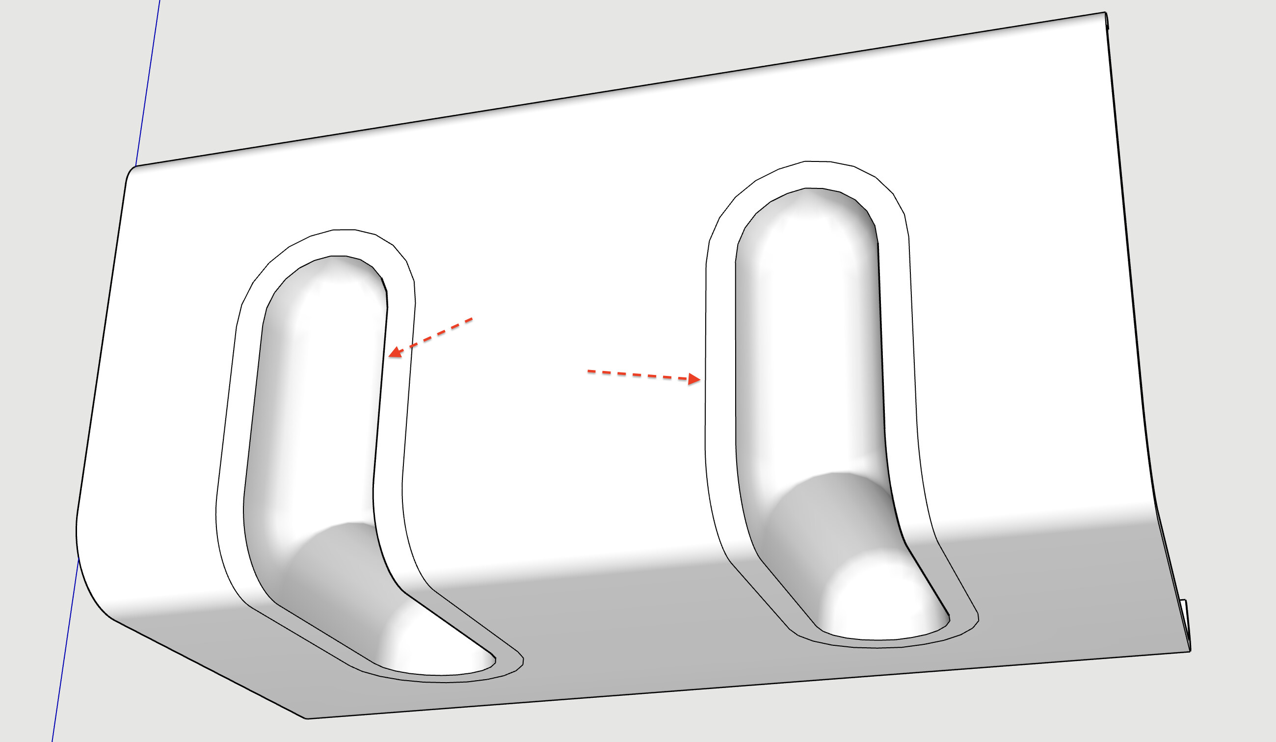
The ‘kink’ is caused by where you bent it. Where you place the tool is where it will bend, so when you used the edge of the shape, the tube part gets compressed. If you aligned the tool with the ‘tube’ it would bend around that point.
It all depends on the exact shape you want.
Thanks @Box, this sequence made all the difference for my understanding the nuances of how to use this tool. I was able to create a reasonable bend, but I keep getting “kinks” in the geometry (image 1). I’m thinking this may be a position issue. This is with soften/smoothing set to 60 degrees. Any suggestions on what I might be doing wrong?
Here is an example of geometry that is a mess ( at least SI2 thinks so ). I can’t read the errors that are noted, way too small. I have have run CleanUp3, no help. How do I correct Surface Borders and Short Edges? Looks like the arcs are a majority of the issues. Thanks for your help.
I don’t know how you created it but the back face is reversed and the other face is missing.
Triple click to select all, shift double click to deselect the front face, hit delete and push to thickness.
You will always get some distortion in an angled bend, that’s the nature of the beast and would happen with a real piece of metal. But it looks like you may get a better result if you align the bend with the end.
See how I select the endpoint as the extent of the bend before clicking.