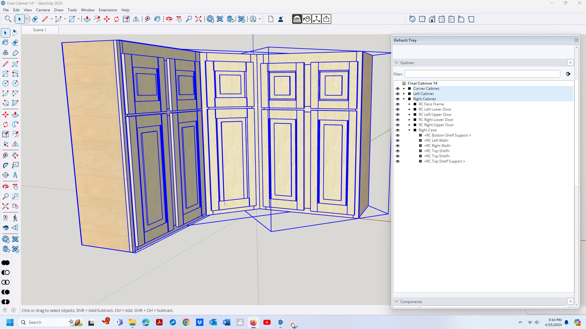
I am trying to get a little more organized as I lean. I have this cabinet divided into three groups, with the components for each section arranged as components within the group. This seemed logical, but I think I may have made it too complex.
The thickness and size of some pieces are not working out. I suspect it’s because I don’t have the Axes set correctly. I was learning as I built this, but for the most part it’s working well. I know now to set my axis when I make a component. Is there a way to go back and set the axis for a whole group of components? And will it hurt for the group axis to be off?
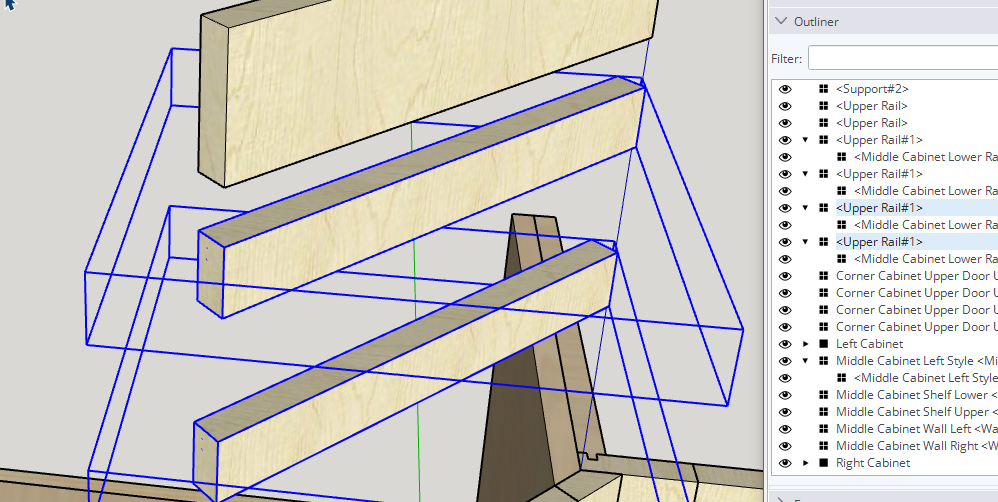
CutList extensions reoprt the dimensions of the object bounding boxes. Components like the rails on the diagonal face frame will be reported with the wrong dimensions because their axes don’t align with the geometry.
You can right click on a component and choose Change Axes. Then set the origin at a corner followed by the alignment of the red and then green axes. Blue takes care of itself.
By the way, before you fix the axes on the two narrower rails there, you should fix the unneeded nesting. No single object needs to be double “wrapped”.
Thank you. I have been fixing “Nesting” all day. I look at that as Components in components. That has been nothing but trouble for me. It seems like components in groups is ok though?
Components in groups aren’t any better. IF you’re going to use nesting the nest or parent object (it can be a component or group and you know which I wuold choose) should contain more than one component. There no reason to put a single component into a group or component. That just makes your work more difficult.
I am doing it mainly to make it easier to find parts and groups of parts. It’s inconvenient that Outliner lists everything alphabetically.
I am able to change the axes now, but I saw you make the blue bounding box of the middle rail conform to the size of the rail. I’ve watched it a dozen times and I cannot repeat your moves. How are you making the blue bounding box fit the part?
First I exploded the unneeded top level component shown as “Upper Rail#1” in Outliner. Then I changed the axes of “Middle Cabinet Lower Rail” and finally, since the bounding box still didn’t fit due to some very short edge segments located over to the left of the rail geometry, I did a right to left selection and pressed Delete.
As for the organization of component names, I guess figuring out what to call things is the first challenge. Maybe give the cabinets numbers from left to right and then these rails might be 2FF Top rail and 2FF Rail. You could give the two narrow rails instances names if you want. Maybe “Middle” and “Bottom”.
If changing axes from native tool is boring, since OpenCutList 5.0, you can use the Orient Part Tools that is a one click tool to adapt part’s axes along the pointed face, even if the part is nested into sub groups
Demo :
More details in the OpenCutList documentation, here.