I know it can be done. I’ve seen it done with Shape Bender, with Joint PushPull, with True Bend, and with VisuHole.
I’ve even been tutored by DaveR on using Shape Bender who took me through to the final product.
But now I’m trying to use Shape Bender to do the same thing by myself and I’m not getting good results.
I drew a solid model.
test - solid group.skp (245.4 KB)
I then used the 3D Text Tool to select the symbols for printing as seen in this jpg, with the vertical bar being U=007C from the Tahoma font.
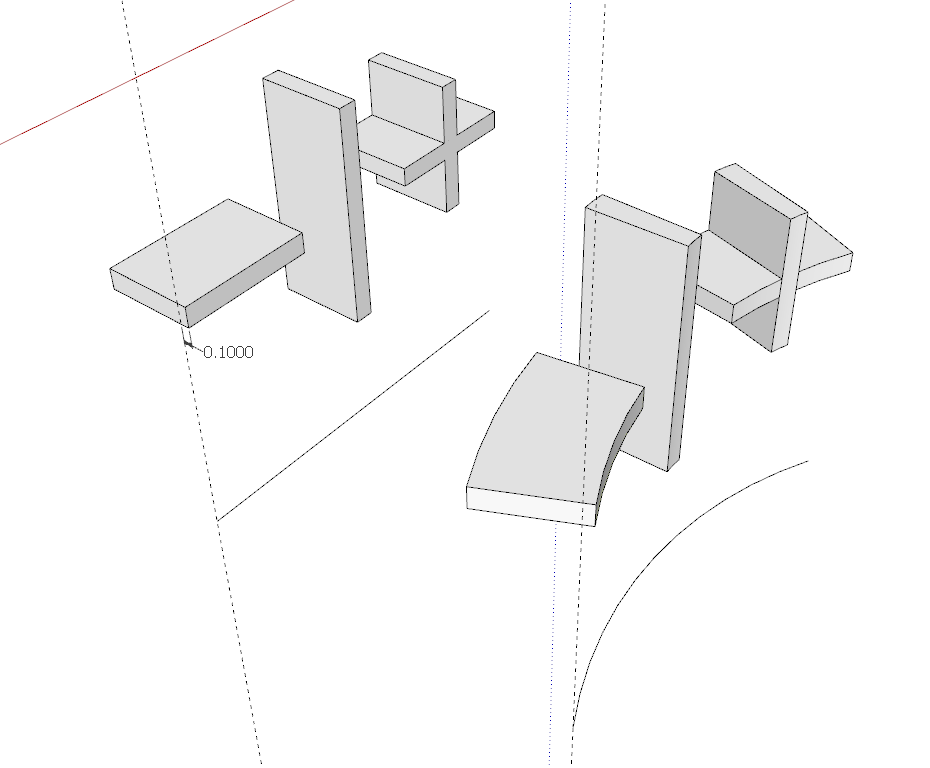
On selecting the Place button, the text component appears flat on the xy plane, where it is supposed to be parallel to the red axis and with its axes aligned with the model axes. Since it was flat on the xy plane I rotated it so that it was in the xz plane (was that right?).
I drew a straight line equal in length to the text component (5.1724").
I calculated the circumference of the model to be 28.95" and from that calculated the degrees of arc necessary to correspond to the length of the text component to avoid distortion. I determined that angle to be 64 degrees.
degrees = 360/(circumference/ line length) = 360/(28.95/5.1724)=64
Then to Shape Bender. The text component was selected, and then the line corresponding to the length of the text component was selected (resulting in Start End labels appearing at each end). Then the 64 degree arc was selected and things started to go south.
test -bent text attached to model.skp (265.1 KB)
The bent component looked distorted and toggling the up/down arrows didn’t improve much but it did get the text into the proper sequence.
Following DaveR’s instructions (to the letter I hope),
So the setup for using Shape Bender is to set the component to be bent (the + | - in this case) so it is parallel to the red axis and it’s axes are aligned with the model axes. Then you need a straight line aligned with the component and a curve as the reference for bending. If you don’t want the bent component to be stretched or compressed, the curve for the bend reference needs to be the same length as the straight line reference. I figured out the angle of the arc required to get the desired length with ϴ=360/(C/s) where ϴ is the angle of the arc, C is the circumference of the outer rim of the cup and s is the length of the straight line.
After getting the bent component, move it into place on the cup, explode the bent text component, Ctrl+X to cut it to the clipboard, open the cup group for editing, Edit>Paste in place to paste the text geometry into the groups. While the text is selected, hold Shift and also select the outside surface of the cup. Right click on it and choose Intersect Faces>With Selection. Then erase the edges of the text that stick out and delete the faces skinning the text. Right click on a white face and choose Orient Faces. I did get symbols attached to the curved face of the model but they don’t look good.
Here’s the final result.
test -finished model after Solid Inspector2.skp (289.6 KB)
PS did I put too many skp files into this question