Hardest thing to get would be the plutonium filament I guess ![]()
3 Likes
It would be cool to have a physical model of the RTG. Full size would be awesome, half size still pretty cool and much more manageable (though minimum wall thickness limitations would cause difficulties here and there). The cut-away version that is seen in the video would perhaps be more interesting than the normal version. Here is a DropBox link to an SKP (2018) file containing the cut-away version of the RTG.
At least such filament would not need to be heated by the printer!
3 Likes
Due to the many overhangs and details, this is indeed a difficult model for an FDM printer…
1 Like
The disassembly sequence at 3:15 is really fun (among many other parts). I’m just learning Fredo6 Animator and have a basic question - when turning layers on/off, how do you make them fade in/out instead of suddenly appearing?
By using a video editing tool. As far as I know, Animator itself cannot gradually change the opacity of objects. So for each point where an object fades in or out, I create two clips: one with the object and one without the object. The clips overlap on the timeline by however long I want the fade to occur (usually 0.5 second in my videos).
I create an Animator visibility control (“purple eye”) in the timeline - located at the time when the fade in/out should start - that turns on or off appropriate layers/tags in the SketchUp model. The Animator function to generate a clip allows the user to specify the start time and end time of the clip, and I use that feature to create the two slightly-overlapping clips (e.g., the first clip covering from 10.0 to 15.5 seconds, and the second clip covering from 15.0 to 18 seconds). I temporarily disable the visibility control when exporting he first clip (covering the earlier part of the timeline). I then enable the visibility control and export the second clip.
The two clips are then imported into a video editor (I use Apple’s iMovie) and a cross-dissolve transition is inserted between them whose duration matches the overlap in the clips.
4 Likes
I’ll give that a try, thanks!
I have completed modeling the meteorology science instruments of the Viking
‘75 Mars lander (3D Warehouse link). All interior details are included (though a few components are only approximated due to lack of sufficient reference material; they are tinted light green in the model). Here is a comparison between the model and actual hardware:

The meteorology subsystem consists primarily of the Meteorology Boom Assembly (MBA) and the Meteorology Sensor Assembly (MSA) mounted on the end of the boom. The boom has a fixed lower arm and a hinged upper arm. The boom is stowed or folded down until shortly after the lander landed on Mars in order to reduce the extended volume of the lander. The meteorology hardware was made by TRW under subcontract to Martin Marietta, the lander prime contractor. Here are views in the stowed and deployed configurations:


It was desirable to place the sensors as far from the lander as practical during use in order to minimize the effect of lander structures and activity on the meteorology readings. Here is an exploded view of the overall hardware:

The subsystem contains over 200 unique components, not including fasteners (of which many types are used and included in the model). All the components are solid in SketchUp terms, except for one that represents an extremely thin metal film that is plated on a 0.02 inch diameter glass rod (part of the wind speed sensor). The boom’s hinge (shown exploded) and sensor assembly (shown cut-away) contain most of the parts:


The sensors measured the near-surface temperature of the Martian atmosphere and the wind speed and direction. Six years’ worth of data were accumulated by Viking lander 1, and four years’ worth by lander 2.
Temperatures were measured by three redundant thermocouples, seen within the fork in the upper right of this cut-away view:

Each thermocouple consisted of a butt-welded pair of Chromel and Constantan wires, 0.003 inch in diameter. Three thermocouples were employed in parallel in case of damage to the fragile wires.
Wind speed and direction were measured by a clever scheme involving no moving parts. In the following cut-away view, wind direction was determined by the so-called Quadrant Sensor at the top, while wind speed was determined via an array of three anemometers (the thick stubby cylinders with needle-like tips) horizontally arrayed across the central portion of the following image:

At the center of the Quadrant Sensor was a tightly coiled heater wire, surrounded by four evenly-spaced fine-wire temperature-sensing thermocouples (very similar to those in the primary temperature sensor fork). In operation, electric current was applied to the central heater. Depending on wind direction, heat would be unevenly carried by convection to the four thermocouples. Wind direction was deduced (to a modest degree of precision) by analyzing the resulting temperature differences.
Wind speed was determined via another application of heaters and sensors in a design known as a hot film anemometer. The left and right wind sensors performed the actual measurements. In operation they would be kept 100 degrees C hotter than the central reference sensor. Wind speed could be determined from the amount of electric current drawn by the outer sensors in order to maintain the 100C difference, as the wind convected away heat from the sensors. Wind direction was further refined by comparing the results from the two outer sensors arranged at a 90 degree angle to each other.
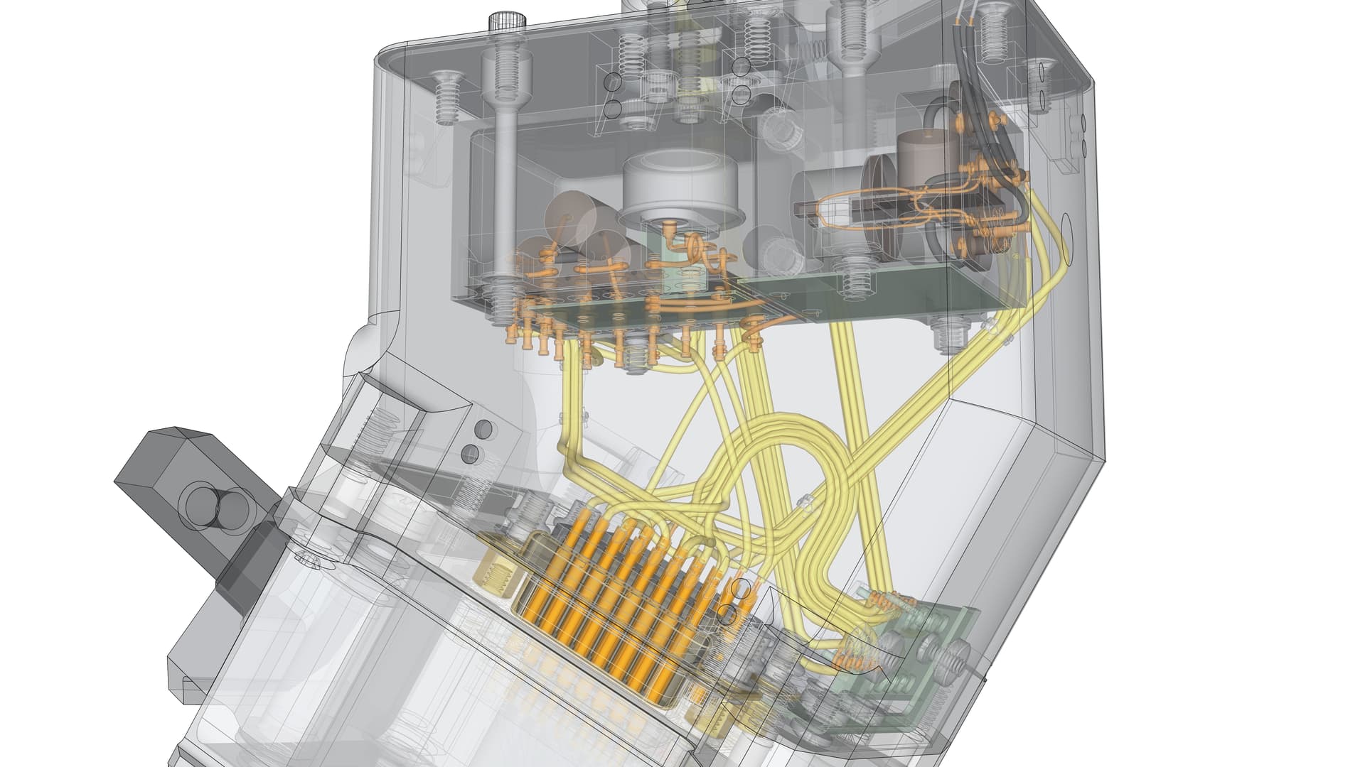
A pair of low level electronics modules were contained within the MSA housing as seen in the following X-raw view, one for the wind sensors (above left of center), and one for the temperature sensors (above right of center). On the bottom of each module is a low-power flat plate heater, shown as green rectangles.
As mentioned previously, the boom was stowed during launch from Earth, cruise to Mars, and descent to the Martian surface. The boom was kept in its stowed configuration by a downlock mechanism, seen here in exploded and cut-away views:


When stowed, a black protrusion near the upper end of the boom’s hinged arm slotted into a cavity within the downlock mechanism. A hole through the protrusion was restrained by a stout rod or “pin”. The pin was part of a pyrotechnic pin-puller device (the bronze colored component) screwed into the side of the downlock body. After landing, an electric current was applied to two redundant Viking Standard Initiators (VSIs) screwed into the pin-puller body. This ignited a small explosive charge, producing a high-pressure pulse of combustion gas which pushed under the head of the pin and forced it to retract into the pin-puller body and disengage from the protrusion on the boom. The coil spring within the downlock body provided an initial push to rotate the boom’s upper arm out of the downlock assembly. The following external view of the sensor assembly shows the black protrusion near the top of the boom more clearly:

Two black curled-up springs within the boom’s hinge provided most of the energy needed to raise the boom, shown in the earlier exploded view and in these cut-away views:


To prevent rebound upon full deployment, a simple uplock mechanism consisted of two redundant flat springs each with a central cut-out slot that latched on a triangular shaped bump on the back of the fixed hinge fitting. One of the two uplock springs is visible in the following view, as a small olive colored component (right of center) with a thin middle and flared thicker lower end.

The two parallel flat uplock springs are more visible in the following exploded view of the hinge (olive colored parts, right of center):

The delicate sensor assembly was protected while stowed by an open-top guard box on the front of the lander. The primary chance of possible damage could occur during the final seconds of landing when the Viking lander’s three terminal descent retro-rockets kicked up dust and possible small rocks. The following images show the sensor assembly within the guard box:


Separate from the MBA and MSA, a cylindrical pressure sensor transducer was located within the lander body, mounted on a dark brown phenolic platform in the following cut-away view:

The lander interior is essentially empty at this point in the model. The dark gray angled flanges (running around the lower interior walls) and the slotted trapezoidal brackets were to restrain insulation blankets that lined the walls of the lander. The loop clamps on the brackets were for routing a tube that vented the lander’s Gas Chromatograph Mass Spectrometer (GCMS) instrument to the outside. A 1/4 inch diameter inlet tube was connected to the end of the pressure transducer, which passed through a fitting in the side of the lander and terminated in a small cylindrical Kiel probe (seen in side view in the bottom right). The Kiel probe and tube supplied ambient atmosphere to the pressure transducer during the last few minutes of descent to the Martian surface, and after landing. Here are other views of the pressure transducer and its platform:


The overall work-in-progress lander model is freely available on DropBox, but beware that the SKP file (in 2016 format) is over 400MB in size. Additional 2D renderings that chronicle this project (just completing its 11th year) are available in a Google Photos album.
13 Likes
Amazing!
Astonishing.
This is a work of love and passion.
WOW!!!
Is NASA aware of all that?
I can see that in a museum dedicated to space exploration. The Smithsonian’s National Air and Space Museum, maybe?
1 Like
I’m pretty much speechless at this point… ![]()
![]()
![]()
![]()
Mind blowing!!
respect
Thank you all for the compliments.
In 2014 I wrangled an invitation to visit NASA’s Langley Research Center in Hampton Virginia, which was the original home of the Viking Project Office. There I met the Langley archivist, who I had learned still had some Viking hardware on site. I spent an enjoyable morning measuring and photographing some components. That person has since retired, sadly. I have not attempted to contact NASA’s overall chief historian; perhaps I should make the attempt.
Regarding the Smithsonian NASM, I have spent time there on a number of occasions studying the so-called Proof Test Capsule (PTC) lander in their collection (my Google Photos album from 2011-2012 and another from 2016). It is the most complete test lander of the four that were build (all of which still survive, and all of which I have visited). Since 2016 I have been in contact with the Smithsonian’s curator for planetary exploration, who granted me some time during a pre-opening morning in 2016 to do close-up photography of the PTC lander (which was undergoing badly needed cleaning and conservation work, prior to being put into a new exhibit space where access is quite limited, sadly). There are possibilities with some other museums and institutions who may be able to use my 3D model in some exhibit capacity.
2 Likes
This is a thing of beauty. I really love the section cuts as well.
I take my hat off to you Tom!
It takes a person with a lot of patience and determination to work on an ongoing project like this for 11 years…
…and counting.
3 Likes