Every time you post a new part I’m amazed again. Your stunning work just keeps going. ![]()
2 Likes
I have recently completed modeling the Viking lander’s two Radioisotope Thermoelectric Generators (RTGs). Here is a link to the model in the 3D Warehouse and some overall views:


Here is an overall cut-away view of the RTG (the model is comprised of solid components in SketchUp terms):

The RTGs are a Viking-specific variant of the SNAP-19 type which was used on earlier spacecraft (Nimbus III, Pioneer 10 and 11). SNAP is an acronym for System for Nuclear Auxiliary Power, which is a series of generators stretching back to the 1950s. Odd-numbered SNAP designs convert the heat of natural radioisotopic decay directly into electricity. Even-numbered designs contain a nuclear reactor in which a radioisotope undergoes accelerated nuclear fission; the resulting heat is converted into electricity in a variety of means.
The Viking SNAP-19 RTGs were fueled with Plutonium 238 in the form of Plutonium Dioxide Cermet (rather than the more hazardous pure Plutonium 238 metal), which is 83% PuO2 and 17% Molybdenum. The fuel was shaped into 18 discs or pucks, seen on the far left in the following exploded view:

Here is an exploded view from below:

The RTG has no moving parts and is completely passive with no means of control. It weighs about 34 pounds and is a bit over 15 inches high (including the dome on top). The span of the six cooling fins is 23 inches across opposite pairs. There are 20,600 curies of fuel (equivalent to a few pounds) sufficient to generate 682 thermal watts from the heat of natural radioactive decay at the time of fueling (which was some nine months prior to launch). At the beginning of the mission the RTG produced about 42 watts of electricity at 4.4 volts DC. The conversion is quite inefficient but the generator has extreme reliability and robustness, and the excess heat was critical to the mission (heating the lander’s interior electronic components).
Electricity is generated via the thermoelectric effect, by which a temperature differential across a thermoelectric couple produces electricity. In the SNAP-19 generator there are a total of 90 thermoelectric conversion couples, each consisting of a P-leg and an N-leg:

The P-leg materials are 15% a mix of Tellurium, Antimony, and Silver, and 85% a mix of Germanium and Tellurium, given the designation TAGS-85, plus a Tin-Tellurium segment on the hot side (on the right in the above image). The N-leg materials are a Lead-Tellurium mix designated 3M-TEGS- 2N(M).
The 90 couples are grouped into six thermoelectric conversion modules of 15 couples each. The following image shows two of the modules in exploded views:

The couples are connected by copper straps. Pairs of couples are connected in parallel, and the pairs are connected in series. The couples in adjacent modules are interconnected by #9 gauge wires, forming a partial hex pattern above and below the RTG core that is visible in the overall exploded views. The full hex wire below the core is a magnetic compensation loop. The hot shoe (inboard end) of each couple is up against the graphite heat shield surrounding the fuel capsule (actually separated from the heat shield via a thin mica sheet for electrical insulation). The temperature of the heat shield surface - forming the hot side of the couple - is about 950F (about 510C). To maximize the temperature differential across the thermoelectric couples, a set of “cold end” hardware provides a thermally conductive path from the copper interconnect straps (which are soldered to the outboard ends of the P- and N-legs of the couples) to the relatively cool exterior RTG housing. The temperature of the exterior housing at the root of each of the six large cooling fins - which are directly adjacent to the six aluminum heat sink bars - is typically about 330F (about 160C).
Starting from the moment of assembly, the RTG power output gradually decreased due to a number of factors:
- Reduction in the RTG core temperature due to decay of the Plutonium fuel, reducing the temperature differential across the thermoelectric couples and thus the efficiency of the thermoelectric conversion process. With a half-life of about 88 years, this was actually not a significant factor during the expected single-digit-years lifetime of the mission.
- Sublimation loss of material from the thermoelectric conversion components due to continuous exposure to high heat.
- Increase in Helium gas within the RTG (produced spontaneously by decay of the Plutonium fuel). Helium has a relatively high thermal conductivity, which lessened the temperature difference across the thermoelectric couples and reduced their efficiency.
The effect of the Helium buildup was partly counteracted by a novel solution. The prominent dome on top of the generator, seen in section view in the following image, is a sealed reservoir filled with a 95% Argon / 5% Helium mix at assembly.

The generator’s cylindrical body was filled with a 90% Helium / 10% Argon mix. The initial high Helium fraction within the generator body was deliberately chosen to reduce the beginning-of-life power output. The months-long series of final RTG tests and storage prior to launch in Earth’s warm dense sea-level atmosphere would otherwise have produced RTG temperatures higher than desired. During cruise to Mars (in vacuum) and on the Mars surface (in a very cold low-pressure atmosphere) a higher energy conversion rate - and thus higher temperature differential - was wanted. The interface between the RTG body and reservoir dome was sealed as described earlier, but with an intentionally leaky seal. A dummy electrical receptacle with a Viton O-ring seal was installed between the body and dome. The dummy receptacle is the threaded object at top center of the ribbed RTG upper cover in the above section image. The O-ring permitted an extremely slow but effective gas exchange between RTG body and reservoir, raising the fraction of Argon (which is less thermally conductive than Helium) in the RTG and improving power generation.
A great deal of effort was applied to mitigate risks of Plutonium fuel release that might occur due to launch accidents (explosions) or unintended spacecraft reentry into Earth’s atmosphere (if the booster rocket did not impart sufficient Earth-escape launch velocity). The following cut-away image shows the RTG’s “heat source” (as the encapsulated plutonium fuel assembly was termed) in close-up:

To mitigate the effect of physical shocks and impacts, the fuel stack (olive-drab pucks) was encapsulated in a four-layer metal capsule consisting of the following, from inner to outer:
- Inner Liner made of a Molybdenum-46% Rhenium alloy, 0.009 inch thick. This is formed of two slip-fit overlapping shells, in direct contact with the Plutonium fuel. (In order to exactly fill the volume of the capsule, Molybdenum shims were placed as needed between fuel pucks. The fuel capsule I modeled, VF-3, has five such shims, three of which are visible.)
- Liner made of a Tantalum-10% Tungsten alloy, 0.020 inch thick. This layer is welded closed and provides the main decontamination and health-physics encapsulation for the fuel.
- Strength Member made of T-111, a Tungsten-8% Hafnium-2% Tantalum alloy, 0.090 inch thick. This layer provides the primary impact resistance necessary in case the overall RTG or a separated fuel capsule fell from a great height onto a hard surface.
- Capsule Clad made of a Platinum-20% Rhodium alloy 0.018 inch think, providing an oxidation barrier during capsule handling. Handling difficulties were exacerbated by the fact that the capsule’s outer surface was thermally very hot - nearly 1400F (about 760C). (The core of the Plutonium was almost 1900F, 1040C.)
To mitigate the extreme heating that could occur if the RTG were to reenter the Earth’s atmosphere at nearly orbital speeds, the above capsule was first enclosed in three pyrolytic graphite sleeves, and then within a large hexagonal heat shield made of AXF-Ql fine grained isotropic Poco graphite, enclosed on both ends with graphite caps attached via stub Acme threads. The graphite is tolerant of extreme heating. In fact two earlier-version SNAP-19B RTGs were inadvertently subjected to moderate re-entry conditions when the NIMBUS B-1 spacecraft to which they were attached suffered a launch abort about one minute after liftoff in May 1968. The RTG housings were completely destroyed, but the heat sources were found and recovered from the Pacific ocean floor in October 1968 and examined in detail. The graphite heat shields were essentially intact.
The SNAP-19 Viking RTG is marvelously simple in principle but subtly designed for extreme reliability.
13 Likes
Shocking detail…
that’s a sexy model for sure…
Fantastic and impressive work.
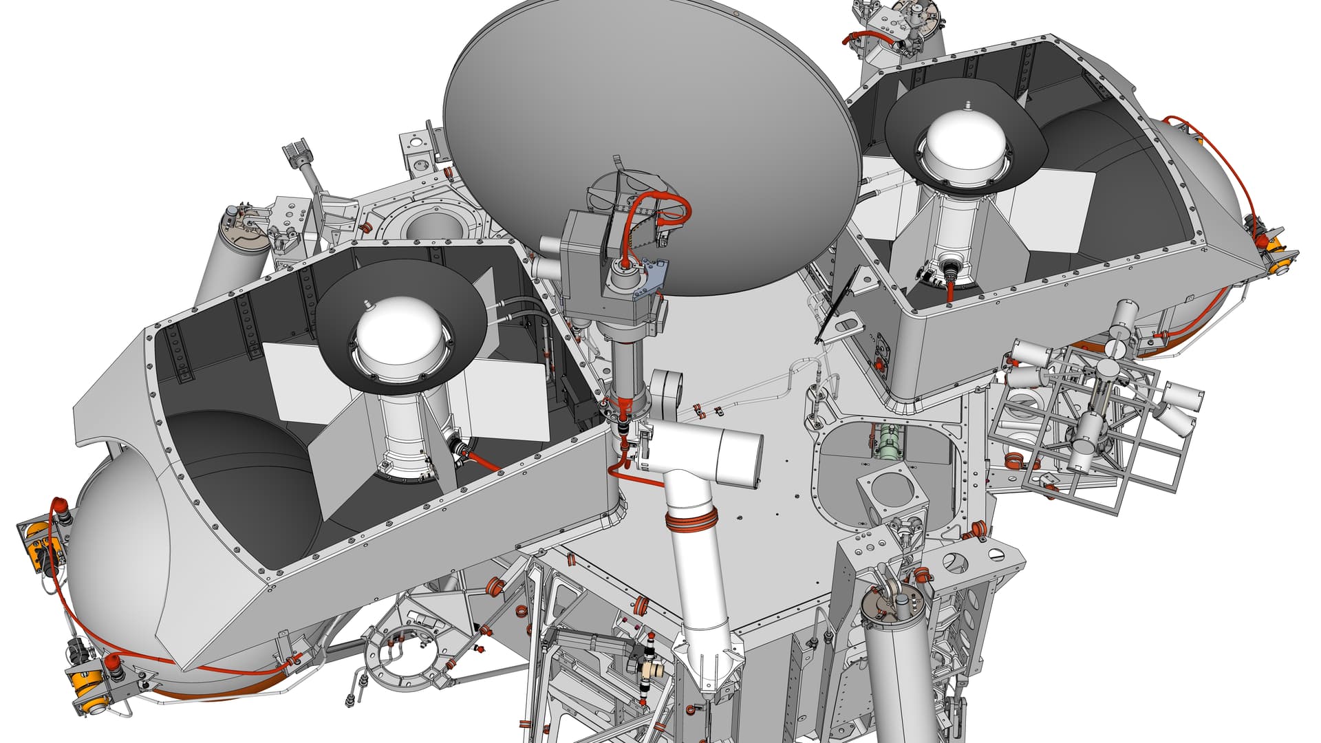
I have completed modeling how the Radioisotope Thermoelectric Generators (RTGs) were integrated into the overall Viking '75 Mars lander. Each RTG was housed within a thin wind cover shell, designed to prevent excessive cooling of the hot RTGs under somewhat unknown Mars surface wind conditions. Some of the RTG heat (that was not converted directly into electricity to power the lander systems) was needed to keep the lander interior warm enough for electronic and mechanical components to operate. These wind covers are some of the most prominent features of the lander, seen here as the large angular objects on the left and right upper surface of the lander body:

Here are views from above without the tops of the wind covers, revealing the RTGs within:

The wind covers are complicated assemblies in their own right. The two wind covers are nearly-identical mirror images of each other. They differ primarily in small items attached to the front face of the wind cover, and that the top of wind cover #2 has an indentation for clearance of the Low Gain Antenna which is located very close to the wind cover. As can be seen in the following exploded views of wind cover #2, each wind cover has internal stiffening ribs along the side and an internal panel near front-center. Each wind cover has a large circular vent on its bottom face near a front corner (visible left of center in the second exploded view below). The vent allows equalization of pressure during launch from Earth and landing on Mars, and is covered with fine mesh to filter out most Martian atmospheric dust. Each wind cover has a camera Reference Test Chart (RTC) attached to its front face. The RTC itself is exploded in these views. A small skirt surrounds the sides and front of the wind cover bottom edge, to minimize build-up of Mars dust under the wind cover during the mission.


Here are close-up views of RTG 2 within its wind cover, starting with a top view. The large conical Upper End Cap Cooler (ECC) is prominent surrounding the reservoir dome atop the RTG housing. The rear rim of the ECC is clipped for clearance within the sloping top of the wind cover. The curving coolant loop inlet and outlet lines are prominent in the upper right of the image. The flat disc radiator fin of the lower ECC blends into the black interior of the wind cover bottom, but it is quite large and obvious when you know what to look for. The rear edge of the radiator fin is also clipped to clear the wind cover’s large spherical inward-bulging rear which in turn provides clearance for the lander’s nearby propellant tank. The large red cable in the lower right carries the 4.4 volt DC electric output of the RTG, along with six instrumentation signal lines (two each for an internal pressure transducer, a fin root thermistor which measured the temperature of the interior surface of the RTG housing, and a Resistive Temperature Detector (RTD) which measured the temperature of one of the thermocouple pairs surrounding the RTG’s internal heat source). The small cream-colored cable passing through an electrical connector near bottom-center delivers the signal from a hazard monitor thermistor which measured the exterior temperature of the RTG housing.


Here is a side view of RTG and wind cover 2 that is cut away to reveal RTG mounting details. The lower ECC has a flattish gray (I believe cast aluminum) body with a somewhat irregular shape. The coolant loop lines enter and exit from the right portion of the ECC body. Four stout tabs (only one of which is easily visible here below-center of the image) mount the ECC, and thus the RTG and wind cover, to the lander structure. The ECC’s two inboard tabs are supported on titanium (for low thermal conductance) U-channel tripods and bipods (with lightening holes) that are in turn mounted to the Equipment Plate within the upper interior of the lander. The green-tinted object between the tripod and bipod and below the RTG front edge is a Thermal Switch for transferring variable amounts of RTG heat into the lander. The ECC’s two outboard tabs bolt to small extensions of the lander body side beam structure. The lower ECC’s flat disc radiator fin is cut away to better reveal the ECC body below the fin. The disc fin is thin on its outer perimeter, thickening toward its slightly depressed center.
The dark conical upper ECC is easily visible atop the RTG housing, and the coolant loop inlet and outlet lines can be seen passing into the upper ECC base. The larger-diameter striped segments of the coolant loop represent braided flexible hoses used in that area. The remainder of the coolant loop is rigid 0.25 inch tubing.

Here are renderings of the coolant loop, from above and below, that was used prior to launch to remove excess heat from the RTGs and lander interior. The RTGs directly generated electricity from the copious amount of heat produced by radioactive decay of plutonium 235 fuel within each RTG. The RTGs and associated integration mechanisms were designed for the Mars surface environment, which is very low pressure and quite cold. Earth’s warm higher-pressure atmosphere caused excessive heating of the lander after the RTGs were installed during the final few months prior to launch. Sterilized chilled water was circulated through the loop almost without interruption (even during the lift of the shrouded orbiter and lander capsule onto the Titan launch vehicle) until shortly before launch. At that point, the coolant was purged with hot dry sterile nitrogen gas, and then a pyrotechnic cutter severed the lines within the Base Cover (top half of the inner layer of the lander capsule). This elaborate procedure was used to avoid unsealing the bioshield (outer layer of the capsule within which the sterilized lander was enclosed) and contaminating the lander with Earthly spores and microbes.
The large black objects affixed to the top and bottom of the RTGs (seen in transparent form to better reveal coolant loop components) are passive End Cap Coolers (ECCs). The coolant circulated through tubing embedded within the ECCs to carry away some RTG heat, and the large surface area of the conical upper ECC and the flat disk lower ECC radiated additional heat.
The loop was also used during the two-day complete-capsule sterilization procedure, temporarily replacing the chilled water with hot water to speed up heating the lander interior (otherwise the lander body’s insulation would require a much longer heat soak period).


15 Likes
… I’m out of words … Excellent!
I’ve mentioned in an earlier reply, but as a reminder the entire work-in-progress Viking lander SketchUp model file is freely available via DropBox. Be aware that the file, saved as a SketchUp 2016 version, is nearly 400MB and contains about 15 million edges and 7 million faces. A few of the sub-systems are also available separately on my SketchUp 3D Warehouse page.
4 Likes
Tom,
An absolute Sketchup masterpiece! Your attention to technical detail and modeling skills are mind-blowing. I mean, even the nut-plate innards are there. I also really enjoy the spacecraft engineering details you provide with each posting.
1 Like
When did you start this project?
The first bits of geometry for the model were created in December 2013. I began a Google Photos album containing work-in-progress renderings in June 2014 to informally chronicle the project. In 2012 I had actually started using SketchUp on a first version, putting in a couple of hundred hours of work into it, when I acquired new significant reference material (a set of blueprints of the core spacecraft structure, posted in another Google Photos album after I had scanned them). That fantastic material caused me to completely scrap the earlier version. That was painful but necessary.
As of now the model has about 1900 unique (all solid) components. The overall model is more than half done, I’d say, considering the major lander assemblies that I plan to model. I am not stressed out about the number of years remaining, it is an enjoyable project. The next few months of my available time (I still work full-time as a software engineer) will be occupied by creating a video about the lander’s RTGs and associated systems. I have created a handful of videos posted on YouTube about Viking so far, using the work-in-progress model to illustrate the topics.
4 Likes
Continually amazed by every new image you post. If there was an “Oscar” for excellence in SU modeling you would have a room full of them. ![]()
5 Likes
bravo!
I have just completed a 21-minute video describing the Viking '75 Mars lander’s Radioisotope Thermoelectric Generators (RTGs) in detail. See earlier replies in this topic for more information about the RTGs.
Many thanks to @Fredo6 for his amazing Animator extension that I used to create the video clips. The 3D model featured in the video is a work-in-progress (ten years as of this month) effort, created entirely in SketchUp.

17 Likes
Absolutely fantastic!!!
Simply brilliant presentation. Bravo ! ![]()
Just wow!
I was going to write “absolutely fantastic” but Guido beat me to it, so I will go with completely utterly positively unequivocally remarkably impressive magnificent and superb instead. I think it’s fair to say you have mastered using SketchUp and Animator.
Great work ![]()
1 Like
Uhh, yeah, what they said. Truly great!
Impressive details and amazing presentation!
Absoluty awesome!!
With the right filaments, @Cotty could make a 3D-printed rtg for his camper:)
2 Likes