I don’t know if i’m doing something wrong here but I cant get the rectangle I’ve drawn to intersect with the wall (below it) then delete the rectangle. Back edges doesn’t show anything out of plane… Anybody’elp me please?
The top lines of the L shaped wall are not quite coplanar.
Either not drawn to be, or perhaps some previous operation has moved some vertices slightly.
If they were coplanar then drawing over one top edge of the L would auto-face the wall top for you - with no need for the rectangle or intersection etc.
As it is you’ll need to triangulate the L shape to get faces.
But then. because of the minimal non-coplanarity you can erase those new diagonals and a single L shaped face will survive.
Alternative:
The flat rectangle is aligned with a vertex, but the rest of the lines don’t intersect with the rectangle.
So try to Move it further down by a few inches and it’ll then intersect.
Erase the unwanted parts of the rectangle and the parts of the L wall above.
Then PushPull or Move the new L top face to the required height…
Drawing over an edge should face the whole L
It did not.
Drawing some diagonasl makes faces.
Removing those diagonals leaves the L shaped face intact.
This suggested that the vertices were not quite coplanar, but sufficiently coplanar to support one face.
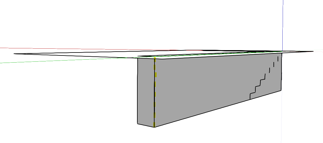
However, looking again I see that the L shaped wall has a tiny gap in one corner so it won’t intersect and form a face !
Thanks for your help. There seem to be so many occasions that tiny indiscrepancies in my (from a dwg imported converted from a pdf via vectorworks and Illustrator) are created because I haven’t chosen a line correctly in the first place to draw the thing. I think it’s possible I’ve yet to truly recreate (in my own work) the legendary planar ‘bug’ that people discuss on here…
One thing that I find useful is to set profiles to 1. Don’t turn them off but just make them less thick. For me it is easier to identify issues such as this. Compare these two screen shots from your model.
With Profiles set to 2 as with your current style.
With Profiles set to 1. Notice that corner still appears as a heavy black line.
Even with the camera orbited around, that heavy black “line” is noticeable.
Dave and Box have already pointed out two of the key techniques. Set the model units to the max possible before using the text tool to label vertices. Drawing diagonals across faces that won’t form is also useful for tracking down gaps and isolated off-plane points in the boundary. Always turn on view->hidden geometry while hunting.
Beyond that, it’s mainly a matter of experience, of knowing what sort of things to look for and how to search them out. In this case the error (a couple mm) was larger than usual, which is why I was embarrassed that I missed it - often they are smaller, sometimes so small that you wonder why they caused any problem!
Clipping is a different issue and needs to be addressed when it arises. If all is right with the world you should be able to zoom in on tiny things. If not, find out why.
Programs like SU have 6 clipping planes; 2 top/bottom two left/ right and two front and back. Those are used to limit the geometry the program has to render.Some programs allow you to specifically set those. I think SU uses the setting you have in perspective rendering and you can set the field of view when you zoom, hold shift key and watch the measurement box.
If I select all the edges on the upper surface (but not the edges), and copy them to the lower surface, I don’t get all the individual faces as I would expect. Some connect together. Can someone explain please?
I can duplicate this effect but can’t explain it except to say that it appears to reveal a bug in SketchUp’s handling of the operation. It is not a non-planarity issue, as all of the vertices test as being perfectly coplanar. But when I move/copy the top inner edges down to the bottom, faces form around the perimeter but I get a single large face in the interior (despite all of the coplanar edges crossing it). It is as if SU gave up on finding faces and quit partway through. There are known problems with inner loops (holes) that touch the boundary of a face. Maybe this is another example.
It is easy to repair the problem: just redraw the center line of the bottom face and SU finds all the previously missing faces.


 I spotted this after closer inspection so I just pulled the right vertical line to the left one


