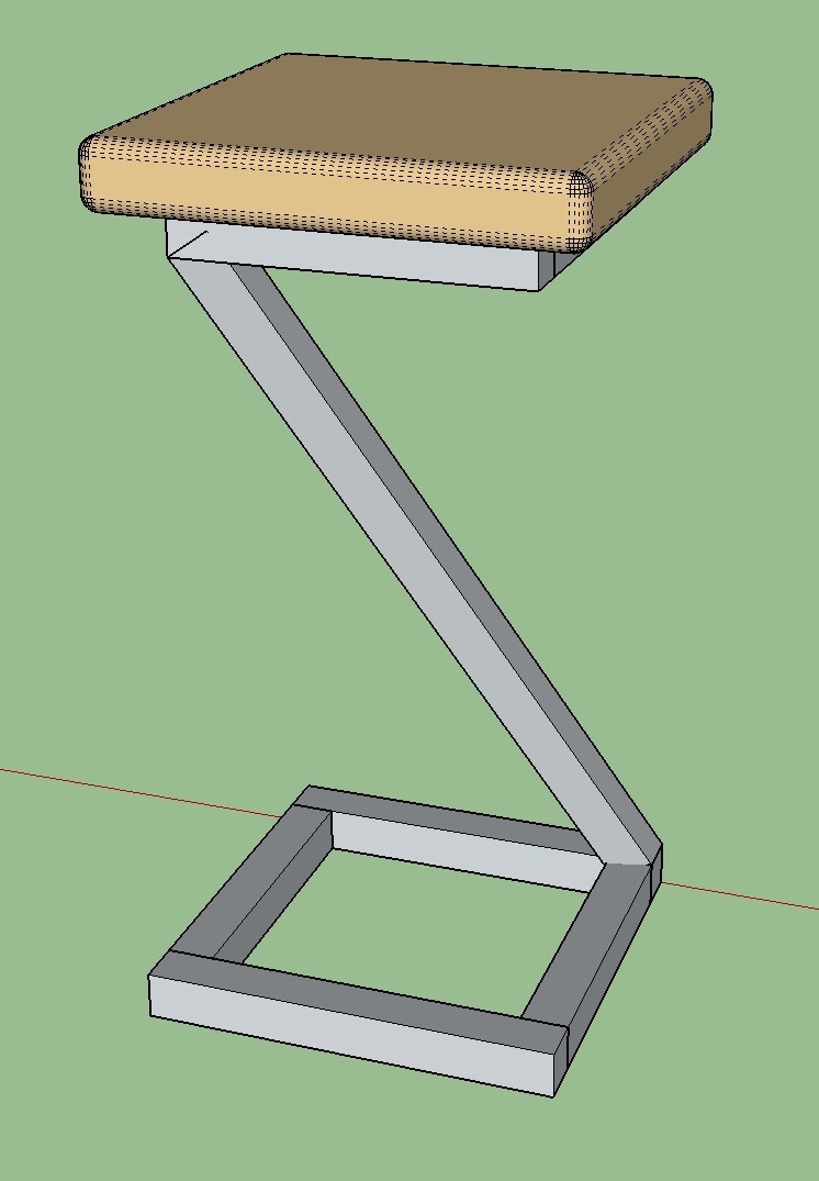
Construction is 1 1/4" sq tube, the idea is the interface between the diagonal and the top and bottom rectangles is square. I was hoping to be able to draw this and then measure the required cut angles from sketchup. If I were to calculate the angles to draw, I wouldn’t need to draw it first, I’d just go and make it!
If someone could outline the steps / tools needed I would appreciate it, I’ve searched the interweb-thingy but formulating a search term to answer this is a problem.
Thanks!
Bob
Model is here: coffee.skp (225.2 KB)
No, just looking to have one leg. Trying a couple of ideas at the moment, but so far I end up distorting the tube in terms of cross section profile.
Thanks.
You could have made a 1 1/4 square and pull it up to the desired height (1’ 8 1/4" I guess). Then you could select just the top surface and use the Move tool to move that 11",11".
Just tried that, nice and simple technique. It looks though as the tube shape has been distorted, in that when I measure with the tape tool, mid section, perpendicular to the edge, it’s no longer 1 1/4"
Going to make an exaggerated model now to check on that…
Thanks for replying!
Bob
The right side I would draw a square of the tube size exactly on the corner,
Make component and push pull top and bottom say two foot further than top and bottom of frame.
Then select it and use rotate tool to rotate to opposite corner using right top of lower frame as a pivot.
Go into edit and draw the lines across top and bot, then push pull excess at top and bottom.
So basically make a vertical part longer, rotate into position draw lines where it cuts and push pull excess.
When you place it hold the mouse button down and drag in the direction you wish to rotate, then let go of the button.
I’m sorry, I didn’t realise the top was smaller than the bottom.? My method may still work but it’s more complicated to rotate if that’s the case. Also the compound will give you a bit to think about trimming top and bottom if that’s the case
Yes, the top is 2" smaller than the bottom (9" vs 11")…
The earlier model I attached may not have had the the two squares properly centered to one another.
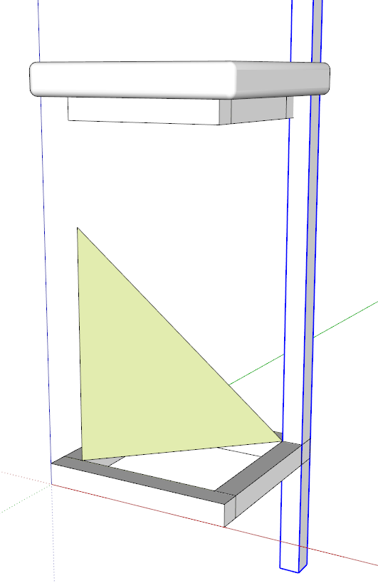
You must have an axis for the tool to work on. In this case you want that axis to be at 45° to the base. I drew in the triangle to provide something for the Rotate tool to inference to. Note, I made the leg much longer than it needs to be so it can be trimmed afterward.
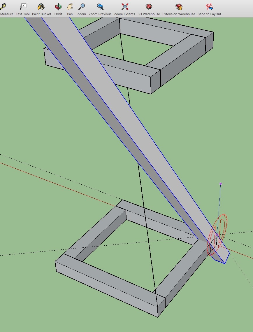
You need to consider what happens at the intersection of the square leg and the horizontal parts when the leg is angled as it is. The cut face won’t be square. It’ll be a parallelogram. And since it isn’t square, there’ll be an apparent misalignment at the ends of the leg. Since this is metal, I expect you can hide that at the bottom with the bead. At the top it won’t be quite so critical.
Important: You were using layers incorrectly in this model. Leave Layer 0 active at all times. And apply materials to faces not component/group containers.
Hi Dave
First of all, thank you! And to Thorleylan too!
I couldn’t for the life of me get the diagonal member to rotate where I wanted it to, ended up drawing another triangle that did work for me.
On the layer use… I have been using layers somewhat ad-hoc rather like I would have in AutoCad. I was intrigued by your comment on layer 0 etc. I searched about and read, for example, this sketch blog The points around organization, faces and edges, makes sense. The only question
I have is whether Sketchup itself treats layer 0 in some special way?
No. It doesn’t other than the fact that Layer 0 is a permanent layer. You cannot delete it or rename it. Layers have only one purpose in SketchUp and that is to control the visibility of entities on them. You would create layers for the components in the model but leave Layer 0 active. Draw the part and make it a component. Then assign the component to the appropriate layer. The edges and faces in the component remain on Layer 0, though. Turning off the visibility for the component’s layer makes the component invisible. It’s sort of like the cloaking device the Romulans had in the original Star Trek series.
Layer 0 is the same as any other, but is the default layer. The general rule is all faces and edges are to be kept on layer 0 and only groups/components are assigned to layers to control visibility of the groups/components.
Never change the active layer in the layers window to any other than layer 0 and you should be ok. This way everything will be drawn on layer 0 as default.
This is a big rule stick to it to avoid confusion, many I see have been warned and ignored it to their inevitable embarrassment later on.
Make you life easily, layout basics in 2d first, 11,11 bottom base, 9,9 top seat, align each center, layout the square corners each , the angle needs to be along the diagonal connect appropriate edges and you are basically done except for the funny cut angles.coffee_MAC1.skp (244.3 KB)
My thanks again to those who took the time to help with this. I thought you might like to see the finished item now it exists in real life. And yes, cutting the diagonal angle was a challenge!