STL looks fine, but prints as a solid

Wow thanks so much everyone I actually missed all this!

Ended up doing it the hardest way possible of coping the lines; pasting them to the other side and spending 10 mins getting it lined up HAHA

But it is done and it works; and to the guy that made the gif… Other people will find that really helpful! Thank you!

Also to the guy that said its the printer… you’re right, It was HAHA, the X axis belt was a lot looser then I thought…Fixed that and got perfect circles. So thanks!

Anyway; this is what all your help has created

The motor now fits perfecting into the blind I have a few more to print; but hopefully will have Alexa enabled blinds by the end of the weekend. Still trying to figure out a way to automate it with tautulli as well so that they close when I start playing a movie.

I think making this was the hardest part though LOL

image

image

1 Like

Glad you got it sorted out in the end! 3D-printing means trial and error in a lot of cases but it’s a fun ride.

Not sure if anyone mentioned this already, but SketchUp Free has the “Solid Inspector” feature built-in and would’ve easily fixed the internal face. Although, it’s certainly valuable to understand how to manually model it correctly.

Solid Inspector is brilliant and will reverse faces, delete stray lines and remove internal faces automatically. It can’t do mind reading, unfortunately.

Coincidentally, I had exactly the same experience as Liminal while printing a test block of nominal 6mm and M6 holes to get the right 3d printing clearances. The four threaded holes printed, the four dowel holes did not print. (OK, OK, I’m printing holes now. :woozy_face:)

I’d used BoolTools2, so the finished drawing was a group. The solution was to explode the group.
M6 3dP Draft Internal Thread dia 60.skp (501.0 KB)

Is there a question with your model?

Why did you have to explode the group?

How much work do you need to do after printing to make those threads usable? What are you screwing into them? The thread profiles don’t match standard metric threads.

Ahh, I was looking for something like solid inspector. But couldn’t find it. Is there some instructions?

My apologies, Dave. I moved my gmail icon and completely forgot about it. :flushed:

I have no idea why the 3d print went wrong, or why it went right after exploding the group. It hasn’t happened again since then.

Generally I prefer to use threads as printed. I use Chinese stainless steel set screws and bolts in M4, 5, 6, 8 and 10, but tend to tap M4 and M5 nowadays.

Oh, yeah. Good spot. I seem to have gone a bit gender diasphoric with my thread forms. I used them in a workholding faceplate for my lathe. Let’s just say I had a senior moment and move on, can we?

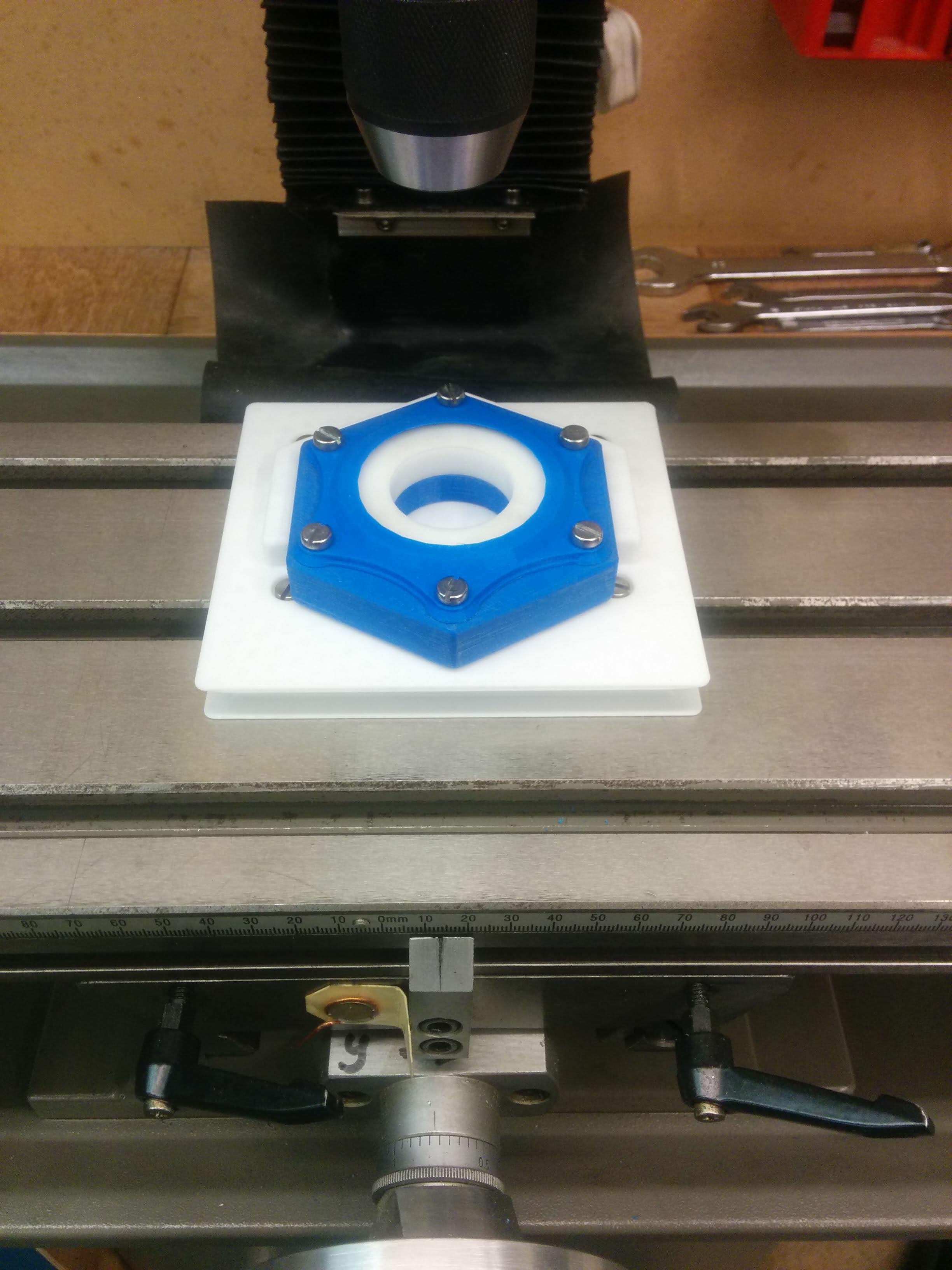
My rule of thumb with 3d printing in general is to use it when I’m happy with plus or minus a tenth of a millimetre accuracy. So I find it useful on my milling machine and lathe for machining plastic components. The attached photo is where I was about to cut six splines into a modified stock plastic crown gear.

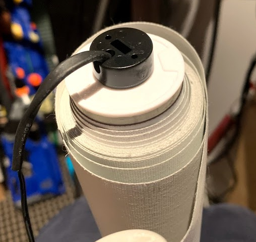
The only thread dimension that needs to be accurate is the pitch. Simply scale the other two dimensions by trial and error. I like the thread to tighten without binding so I can bring the mating faces together and then pull them tight with a final eighth or quarter turn without fear of stripping the threads. For slotted or pozi fasteners, I like ten threads. As for spanners, twenty threads seems about right, although I’m only guessing. A major drawback with 3d prints is layer adhesion, so the limiting factor is the weakness of the material. At twenty per cent infill, you’d be winding your bolt into the material and crushing it before stripping the threads.

The dark art that is 3d printing means that as you change your material, hotend temperature, layer height or any one of many variables, the thread just isn’t right any more. You can’t draw one thread that is going to work all the time. The one thing that never changes, though, is the pitch. For me, 3d printed threads in M6, M8 and M10 definitely work, and when you’ve got the diameter right for your particular application, you can be sure the threaded hole is right where it is supposed to be, within the limits of your machine. That’s the best possible, and when it is all done, it’s difficult to avoid being satisfied with the effort involved.

Thank you for your response. Again sorry for not responding sooner.

For parts with any stress to them need at least 80 % in fill or there will be problems like breaking off . . I got my settings in Marlin so a part made to 20 mm is 20 mm in size . . I use Pruse Slic3r for G-code and Repetier-Host for Printing with My I3 Pro C Dual Extruder 3D printer ( got part made by or sent out by Geeetech made with must have been 10 % with the big empty spots in it and the broke )

Interesting design of printer, Lynne, and a decent build volume.

I haven’t used calibration settings though they seem an attractive idea.

Across flats, the hexagon piece measures 86.49, 86.71 and 86.59 mm. The drawing is 86.60 mm a/f. As for infill, the setting here is 20%, cubic, with double lines, and in reality it is actually 50% infill by weight so I’m not that far behind you on this aspect.

Thanks for posting. :grinning:

Remember this is for a I3 Pro C Dual Extruder 3D printer NOT YOUR PRINTER ! Have to look for this area in Marlin And Adjust to what makes parts the right size . . I use Marlin 1.1.8 as it is quick and easy to adjust . . and I use Ardunio 1.8.5 to upload and verify the changes . .
/**

  • Default Axis Steps Per Unit (steps/mm)
  • Override with M92
  •                                  X, Y, Z, E0 [, E1[, E2[, E3[, E4]]]]
    

*/
#define DEFAULT_AXIS_STEPS_PER_UNIT {79.85, 80.05, 2140, 80 } // X 79.8 to 79.85,- Y 80.1 to 80.05 and 2120 to 2140 and 95 to 80 8-20-19 2140 79.9 to 80

/**

  • Default Max Feed Rate (mm/s)
  • Override with M203

THE “//” part in the settings is for me to know what I changed and how much I changed it and date I changed it . . the Printer will NOT READ the spot after //

  •                                  X, Y, Z, E0 [, E1[, E2[, E3[, E4]]]]
    

*/
#define DEFAULT_MAX_FEEDRATE { 400, 400, 4, 45 }

Thanks, Lynne. It’s a bit too advanced for me for the time being. Luckily, my printer produces accurate dimensions. Firmware changes are definitely something I’d like to address in the future, though.