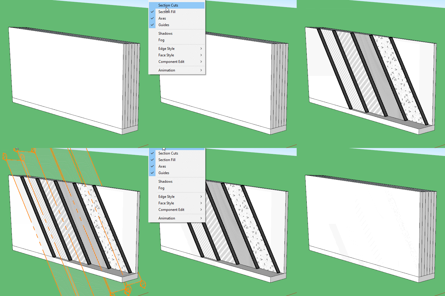
Am I doing something wrong? I am modelling a bathroom and in particular, the layers of construction that I would like to show on the inside face of the bathroom. I was intending to illustrate a 1:20 detailed plan in Layout that shows these individual layers: existing wall, plaster, tile backer board, adhesive and tiles. I am modelling these layers by offsetting the floor by the incremental thicknesses and extruding these up to the ceiling level. My problem is that some of these layers show up in a horizontal plan section and others show as an open void. I have checked in X-Ray view that each layer is joined and all corners are complete by a vertical line in each of the four corners. In a normal plan view, the individual layers are visible, but in a plan section, some wall build ups merge into one thick wall, and others have a void in the middle of the build up.
Is there a minimum thickness that SU can display individual layers or an adjustable tolerance for fill to be displayed? The narrowest layer that I am modelling is 10mm.
Also, I have noticed that in a plan section, the entire room is shown filled, which is at odds to the way it displays in a normal top view - the room is modelled as a void.
What am I doing wrong.
I am using a Default Style.
That’s a lot of words with no images or model.
Either or both (the model is best) would help us help you.
Sorry, I wasn’t sure how to upload images or a model.
I have recreated the issue in the attached file which is a simplified version but shows the same section fill issue.
Section fill issue.skp (357.6 KB)
Think of it this way, all your geometry, thus the closed loops of your (material) layers are in the same context. There is no wall object, nor a plaster object, nor a tile object. The section cut > fill operation uses two outer existing geometry loops to fill, then the next two, etc. In between two fills there is nothing to fill, there aren’t two loops to use.
Solution: think of real objects and create them as such: a wall group, a plaster group, a tile group, etc.
They all will have theyr own skin, an inner and an outer face.
In other words: section cut > and fill doesn’t use any loop twice.
See:https:
So, essentially, I will need to model the individual layers as you describe as separate groups and put them together, face to face (as they would actually be constructed). Although this is a more work than I had anticipated, I would like to be able to represent the project properly. Many thanks for your very helpful reply.
Yes, exactly. It’s not that much more work. Create the floor > offset the wall thickness > the plaster > the tiles.
Double click the wall face > create group
Double click the plaster face > create group
Double click the tiles face > create group
(double click the floor face > create group (it wiil be the inner perimeter of the floor, you might want the outer perimeter though, where you started from / meaning slightly different workflow))
In each group’s editing context pull the face to desired height.
So very fast you end up with proper separation of geometry.
If you do your grouping correctly you can put sections into the groups to give a more layered view of the structure than a simple slice gives.
