Top and bottom ‘follow me’ extrusions are supposed to be solid as per model… did some searching, tried some extensions I’m probably 3 hours in to trying… anyone help?
Thank you
Wendys Letter Tray Riser.stl (487.5 KB)
Top and bottom ‘follow me’ extrusions are supposed to be solid as per model… did some searching, tried some extensions I’m probably 3 hours in to trying… anyone help?
Thank you
Wendys Letter Tray Riser.stl (487.5 KB)
Weird, I don’t get those numbers when i run that extension. And honestly, I have no idea how to fix that anyway!
skp attached, thank you for the super fast reply!
Wendys Letter Tray Riser.skp (489.8 KB)
That’s because the geometry in the .stl is ungrouped. It’s why I asked for the .skp file instead of the .stl.
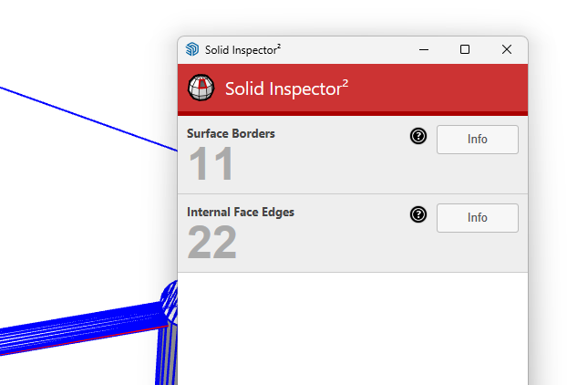
In your .skp file I get this first:
When I open the top level object I find the things at the top and bottom are groups with the geometry in between ungrouped. You can’t mix groups and ungrouped geometry for the object to be considered solid.
And the top group shows these errors.
You need to fix the holes and internal faces in the groups top and bottom and then group the vertical rods separate from the top and bottom groups and make sure they are also solid.
When I add a section cut to the bottom group internal faces and even a hole are visiible.
Thanks Dave, appreciate you having a look at it for me. I think that’s proof I’m a rank amateur! How do I fix that? I did try closing the gaps that the ‘follow me’ left between the semicircle and the straight pipe, but it was very inefficient, and messy. I had hoped that as Follow me was a built in tool, it would do any necessary tidying automatically.
I’m working through redoing the end pieces to make them work more easily in the modeling process.
Follow Me is just a tool. The quality of its output depends on the input. Actually it would probably be better to model that portion of the thing differently. Did you intended to have an elliptical section on these parts?
What dimensions and information were you working from to model this?
Is it really supposed to be more than a meter and a half wide? I’ve got a big printer but it couldn’t handle 3D printing that in one piece.
Amazing, thank you so much! No, they’re supposed to be circles, i don’t know how they’ve become eliptical!
I’m trying to replicate a tray riser i have in my hand… some of the dimensions are important, most aren’t so it’s not an accurate model… let me add some ‘critical’ dimesions to the model, and I’ll submit that too.
Thanks again Dave!
You’re welcome.
Typically that’s due to incorrect setup of the profile and path for Follw Me. The profile must be placed perpendicular to the first segment in the path. If it’s not, the profile gets projected, not rotated, to perpendicular. Also the extrusion will end perpendicular to the last segment in the path.
FWIW, I would do this modeling with units set to meters and treat millimeters as meters. This will help prevent some issues with tiny faces which result in holes in surfaces. It also allows you to use more segments/sides for edges of circles and arcs so you can get smoother output for printing.
So it looks like the hooks at the ends have a curved transition into the straight section instead of the sharp corners you’ve modeled. Is that right?
Doesn’t matter either way really, if it’s easy, smooth would be great!
Smooth is probably easier.
This doesn’t follow any specific dimensions but you should get the idea.
I drew the path using a circle and a traight edge joined with a arc. I added a little edge segment where I want to break the circle. It and the selected portion of the circle will be deleted. You could draw the arc with the Arc or 2-Point Arc tool instead of the circle. In this case I used the circle to give me a visual reference for where to add the straight edge segment.
Here I’ve extended the end of the arc a little and added a circle for a profile. Then I rotated it to the required angle.
Using Flip, I copied the path to make the other half. I then added an arc to make a smooth bend at the center. I moved the profile circle vertically so I could leave the path where it’s easy to see. After running Follow Me and making the thing a component, you can see that SketchUp identified it as solid.
Even if you did something in the process that resulted in the thing not being a solid, it should be easier to clean up because of the smooth changes in direction of the path.
That looks great Dave, thank you so much, just the ticket. Are you sending the skp file over?
Here you go. I’m sure the dimensions aren’t what you want but you can poke at it.
bent wire.skp (840.3 KB)
Awesome Dave, thank you so much for spending time on this for me. The MIL will be happy!