I am trying to reverse engineer a plastic housing, the housing is in 2 halves and there is a slight taper inwards of the walls by 0.5mm per side, I have managed to achieve that with the help of tutorials and google etc.
But I am now stuck as I have to create a 3mm cutout on one of the bottom edges, the cutout is perpendicular to the base, but of course the walls are tapered and this means that when I try and push/pull the cutout, it pushes perpendicularly and I am unable to get it to push based on the angled wall.
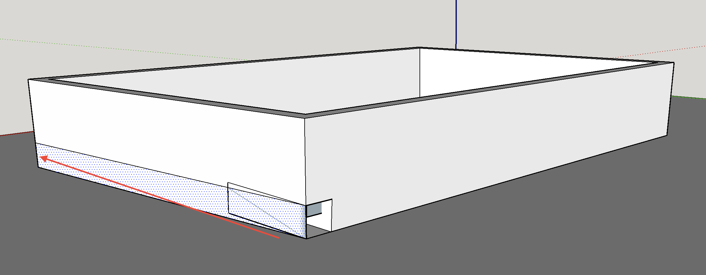
This is pretty difficult to explain with words, so I have attached an image, you can see that I have drawn the 3mm cutout on the front left edge, but when I try and extend it backwards, it goes inwards and upwards instead of following the direction of the lower edge.
I also tried drawing the section all around the 3 affected edges, and pushing from the other (left) edge inwards but that does not work either, the push pull always seemd to be perpendicular to the base, even if I drag it to the edge ?
So how can I create this square cutout on my housing that has tapered walls ?
Is that supposed to leave a slit through to the inside of the box?
Probably the easiest way to do this is draw the square face off the box and make it vertical. Then you can extrude it through the box. Select all of the geometry, right click and choose Intersect Faces>With Selection. Delete the unwanted bits and correct the face orientation.
Thanks, but I am a only 1 day into this and have never used a 3d program before, so that’s quite a lot for me to understand, I will try and see if I can figure it out.
It’s not supposed to cut a slit through, next thing I need to figure out is how to keep the bottom floor of the housing where the 3mm slot cuts through, but one step at a time !
Sorry. I was doing that as I put my shoes on to leave for work.
If you don’t want the slit through into the interior of the box, do you want a step on the inside or do you want ot make the end wall thicker all the way up.
By the way, you can triple click on the box with the Select tool to select all attached geometry, too.
I am making progress, I have managed to cutout the slot, but because the slot width and height is 3mm and the wall is tapered, how do I accurately position the cutout box so that it is exactly 3mm wide at the base ?
Also, you’re rightI need a step on the inside that has the same 1.5mm wall thickness as the rest of the base of the box.
I’m not able to upload screen shots at the moment because I’m on my phone but…
First, think of the rectangle I showed in my earlier screen shot as a cutter. When it gets extruded with Push/Pull, it is representing the volume of space the cutter would pass through as it cuts through the box.
In your case, then, you would need to modify the cutter so it has the required angle which matches the angle on the outside face of the box. You can use a few guidelines placed with the Tape Measure tool to help you sort that out. After you extrude the cutter, select its faces and only the outside faces of the box using Shift with the Select tool. Then run Intersect Faces>With Selection. (using With Selection gives you control over what gets intersected.) And erase the unneeded geometry.
You can use the same idea to create the step on the inside of the box using a larger cutter.
You could also make a cutter in the shape of an inverted L and use that to generate both the step and the notch in a single step. You just have to keep track of which edges and faces need to be deleted.
Well, it can be done but you’re likely to wreck it and make it hard to fix. It would be easier to restore the cutout and redraw it so it’s the right size.
How did you draw the initial rectangle on the side without it being angled the same as the face, but instead keeping it perpendicular to the xyz axis ?
If I draw it on the face then I get the initial problem, if I draw it completely outside of the existing box, then I cannot get it to align with the side of the box.
I filled in the slot using 7 lines, but when I then pull the surfaces up and out from the inside it pulls it away from surface I have just added in, not sure if you understand ?
I do understand. Don’t use Push/Pull to try to fix this. Use the Line Tool.
By the way, I think the issues with the dimensions being slightly off has to do with the way SketchUp’s Dimension works. Because the faces on the sides of the box aren’t aligned on axis, the distance you are measuring isn’t actually the correct distance.
This is what I tried to describe earlier.
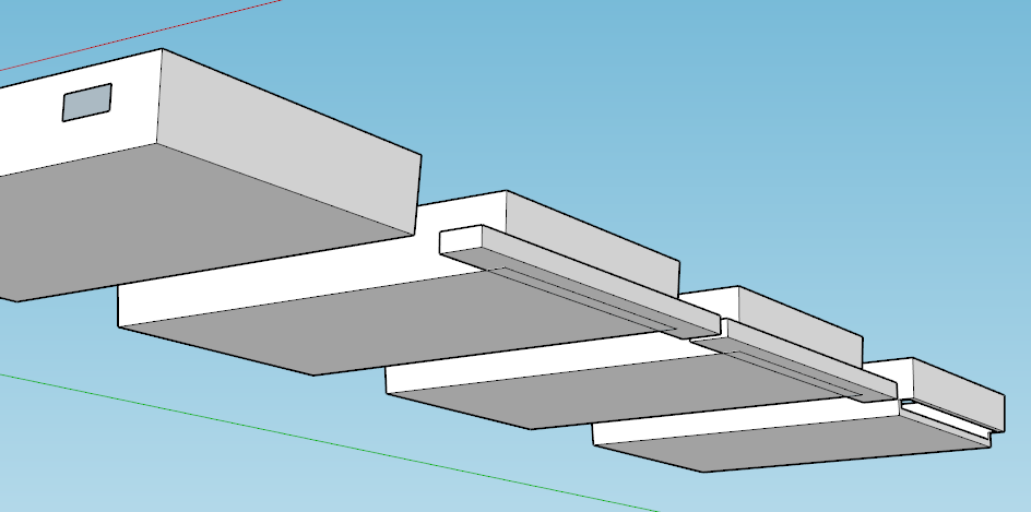
Here’s a parallelogram with sides exactly 3.0mm I made the angle match the angle on the exterior wall of the box.
I added some edges to the parallelogram for what will be the 1.5mm wall thickness in the step area. I did extend the horizontal part of the L to extend beyond the box. That just helps to make it easier to select faces and clean up later.
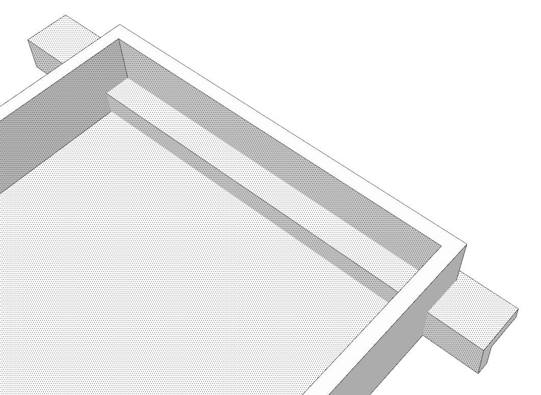
With Push/Pull I extruded the L through the box and well out the other side. Then I selected the faces shown as well as the inside near face before running Intersect Faces>With Selection.
I repeated the intersection operation after selecting the outer faces.
I am also trying this, I have started again from scratch, using what I have learned so far.
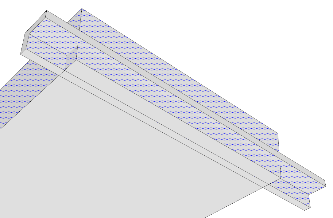
I have made the L horizontal 5.5mmm wide (0.5mm longer), and thought that I could add a dimension between the left vertical of the inverted L and the main box housing and then drag it backwards until it was exactly -5.0mm from the edge, but the dimension snaps but won’t lock onto the edge of the inverted L as it is not a corner or midpoint.
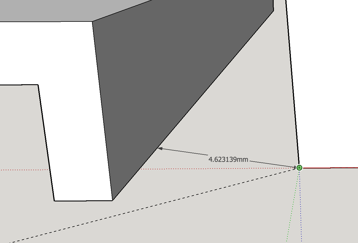
You can see in the image the dimension is 4.623 but it will not lock onto the edge, if it did then I could just slide it back until this was exactly -5mm *1.5mm wall + 3mm slot) and it would be perfectly located.
So although I now understand the inverted L concept, I am still unable to accurately position the L so that it is exactly 3mm in from the base ?!