Naming for Dynamic Components

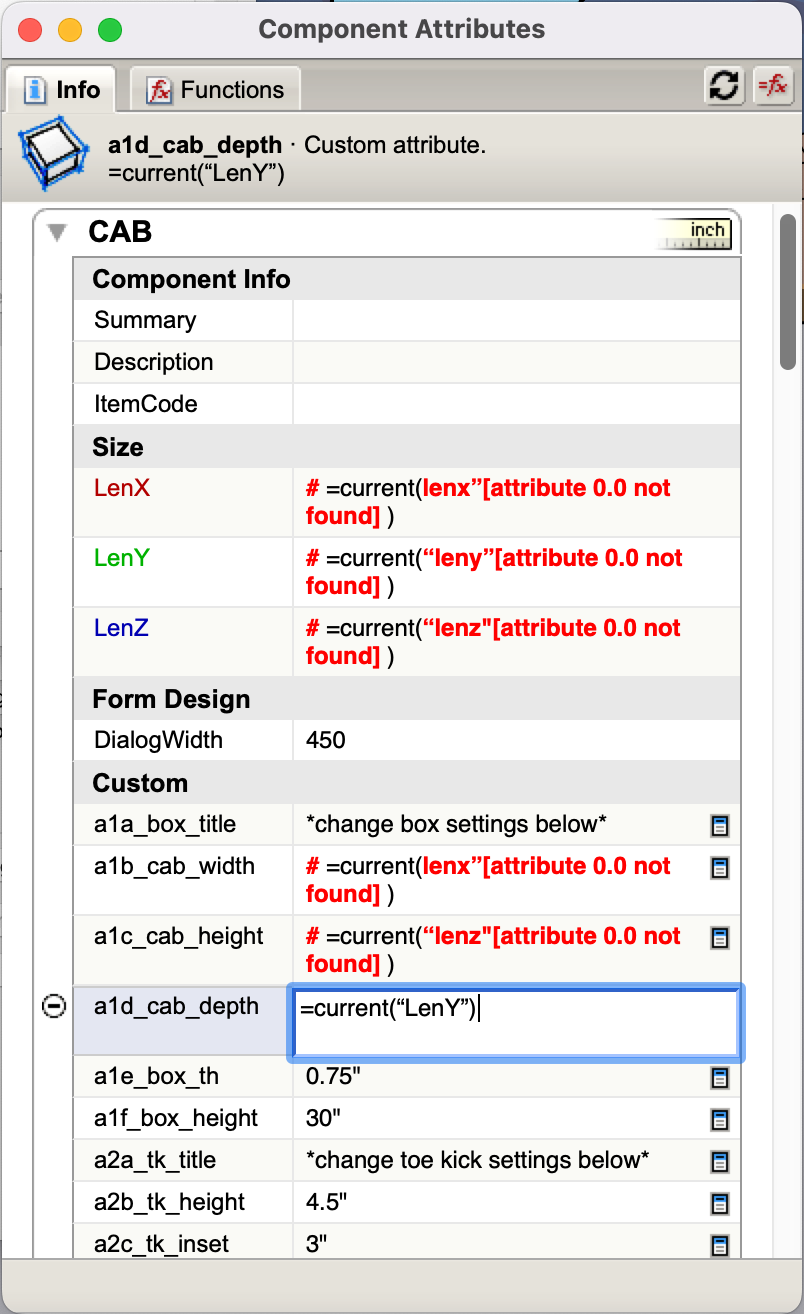
I’m getting ready to embark on the journey of creating dynamic component asset libraries for my design company. I have experience building some DC’s for windows, doors, and trim, but need to start from scratch as the window DC’s I made are too file heavy (I used the cad profiles from the manufacturer to create the extrusions I made the parts from and there are a lot of lines and curves to them). I am looking for advice for naming standards and organization from anyone with experience on what works the best. For example, should I name custom attributes with a letter/number system like “a1a_attribute name” or a double letter system like “aa_attribute name” or some other system that works well? Basically just wanting to get the systematization right before putting the weeks of work in on this. Also, when naming component headers, is there a reason why I should name things differently for each component type or can many of the names be the same across different components? For example, if I am creating a casement and an awning window, should the parts be named with the prefix WIN_CAS_(Part Name) or WIN_AWN_(Part Name) or can they all be simplified with WIN_(Part Name)?

Interested to see what the DC ninja’s have found works the best. Appreciate any feedback!

1 Like

I’m also curious about what works best for axis location. I’ve seen some components where the blue axis is facing out instead of up. What is the reason for doing this?

Good evening
The naming of the definition should reflect how you will later search for the object.
Terms or abbreviations must characterize from the most generic on the left to the most specific on the right.
Thus, in a list of components sorted in alphabetical order, you can easily find the component.

Knowing that the name of the definition is carried around in the attribute references for the formulas, it should not be long names.
A lexicon of 3 alphabetical digits already allows you 17576 combinations.
Personally, I opt for
On an organization Over-family, family, sub-family
OFA_FAM_SFA
Then a quick description of one or two words
PVC tilt and turn window ref 1578
WIN_TAT_PVC_1578_white
WIN_TAT_WOO_1358_oak

WIN_TAT_WOO_1358_oak_2022

This is where the description attribute comes into its own to confirm that the correct component has been selected.

For the names of the attributes, they must be short, because they are constantly manipulated in the formulas.
The order of appearance in the component options window is alphabetical.
So personally, I opt for a 3-digit prefix to create the attribute categories, then a 2-digit numeric prefix to order the attributes within the groupings if necessary.
And finally a meaningful name that describes the attribute.
dim_01_lenx
dim_02_lenxmax
dim_03_copies

so you can easily create grouping titles by creating an attribute of the category name
dim =“### DIMENSIONS ###”

After on simple components, we can get rid of that!
I hope this has been useful to you.
And you others?

1 Like

@simjoubert Thank you for this information! To clarify:

Do you mean search for the object on the 3D warehouse or the Outliner? or both?

When you say terms/abbreviations - are you referring to the naming of each component part that shows up in the header of the attribute window?


This name can be different than the name that is given to the component when creating it and shown in the entity info window, correct?

If you wouldn’t mind, it would be helpful for me to see a DC you’ve created that demonstrated your system for model organization. I appreciate your help!

Thanks!

Also, often when I am working on creating a DC, the DC Options window is blank and says “No Components Selected” even though I have components selected. Any fix for this other than restarting SU?

I talked about the issue, and work around, here:

Hello
The DC panel option and the DC manger have not the same view !
All attributes are visible in the manager , but in the option panel only the attributes that have the meta attributes acces fixe to VIEW, TEXTBOX, OR LIST are visible.

Be careful not to mix up definitions and instances.
The definition is the recipe for the cake, it’s immaterial!
the instance is the cake made by following the recipe, it’s material!
The instance and the definition each have their own name.
To this, dynamic components can change the name visible in the option panel by creating a name attribute.
In the manager panel, the name displayed is in descending order of priority
the definition name, if the instance name is not specified,
the instance name if another value has not been defined.
The latter is practical to avoid having reference problems in the formulas, if ever the name of the instance were to be modified. And cascading break the bond.

If you use the instance name method, then the headers in the option and attribute change with the instance name, so no point in being specific when creating the DCs. So start with one simple rectangular solid, add the attributes commonly used and any for the reports, avoid using the Name attribute as this will override the instance name. For this template DC, you need to saveas then bring it back into a new or purged of this DC file, this will activate the connection between the DC and instance names. Then you can create a range of basic DCs using this template, via right click menu, making unique and scaling definition if required then saveas to a folder. For any child component or group after creating them, change their reference to their parents title to the generic, that is …

myDCparent_somename!an_attribute
to
parent!an_attribute

then you can change the instance name without effecting the formula

see a file with more detail, the parts are all generated from the simple one, then put together to create the object, this is saveas and brought back in to a clean working environment to activates its instance connection

Axis to a certain degree is important, I first started follow the Sketchup using Y as my length with x-z as the profile, now because of materials I am converting to Z, so grain flows in the Z direction or you could use the X, either way you would create your material folders based on the choice.

The x/y is always the gluing and cutting face.

At this point, as the position and rotation of components is somewhat fiddly, you should consider using scripts, like one that accesses your folders, and places the component within two or more points, scaled and rotated in one action, Such script would be personal to your DC sets. For this, the axis and insert point for the parents would all be the same.
Other scripts could freeze and simplify the heavy DCs somewhat like the new Live components (although this concept predates them) reactivation is simply done by swapping the instance with the folder saved version of the DC.
Swapping DCs with other DCs and connecting similar attribute values is done by using the Current formula and having a lower nesting read the values. (an extra level, a good point in the simplification, or where formula is kept leaving the parent to collect data)

I use simple attributes relevant to the context, specific attributes to report data and use the a,aa ab, just in the parent to organise the positions in the option dialog

1 Like

example of using a script to place the DC

Hi Philip,

Thank you for this information! It sounds like you have a lot of experience streamlining the process - but honestly - a lot of it went over my head. Is there any way you could put the above info in more of a simplified step by step process in chronological order of operation? I have no experience with scripts at all, and I am interested in creating a “dummy” DC that would save time but not sure I understand the big picture process. I also do not know what you mean by “descale group”. could you please elaborate on that? Thanks!

@pcmoor ,

Have you found an efficient way to replace formulas that reference a parent attribute with “parent!” I’m thinking something like a find and replace within the DC attributes?

Here is what I have so far as the start of my base cabinet component. The functionality I want to build into it is:

  1. User ability to change cabinet width, height, depth, and frame thickness from a text box
  2. User ability to change toe kick height, inset, and finish thickness from a text box
  3. User ability to control toe kick end edge visibility so if you are stacking cabinets together the toe kick looks seamless, or if one side of the cabinet has a finished end panel the edges are visible.
  4. User ability to display a piece of filler trim on the left side only, right side only, none, or both and the ability to change the filler width of each side independently.
  5. User ability to display a finished end panel on the left side, right side, none, or both, and change the thickness of that panel.

I think I am making progress, but one question I have is whether I should use the copies feature (as currently built) for the box sides, box base and top, filler pieces, and toe kick end pieces. This seems to work with the formulas I have so far but I am wondering when I add the material functionality if I will have problems with which side of the component is displaying the material. Also, I have some hidden edges on the box sides so they mesh with the base, but I had to flip the vertical box piece copy along the red axis and I am not sure if flipping things is OK, or if I should stay away from doing that. I did it this way because I was thinking of trying to keep overall file size as low as possible, but I might be causing problems. Should I instead be adding parts as left, right, top, bottom, vs. using copies?

Also, if you look at the attached picture of the outliner, why does the BOX_H copy keep the same component definition, and the BOX_V copy makes a unique component?

If someone could check my formulas as well and let me know if I am on the right track with those, I would appreciate it. Thanks for your help everyone!

Working Cabinet DC.skp (408.4 KB)

You can discover the instances of the text using control F, however there is no replace, this is probably a web feature rather than a Sketchup tool. If the instance connection works, one can change any long titles to XXX, do a copy of the parent term using control C, then change to Fx display, double click the XXX, which should stand out, control V, and enter after replacing it and any others in the cell
If you are altering a component for your own use, then delete the “Name” attribute(s), if this does not work, it means that the title has been manually changed, so for these children you would need to saveas to a temp place, then purge it from the object, then bring it back in.

I will upload some videos to my YouTube account later, there are some there that might help
psm2000

@pcmoor I am not fully understanding the instance name concept. I can change the instance name and the headers change to “Base Cabinet with Drawers”. I then do a save as and import the component into a new model but the instance name clears and reverts back to “CAB”. If I want the name “Base Cabinet with Drawers” to be what appears when inserting the component, what do I need to do differently?

The inserted component definition resides in the file you have, what you see is an instance of this definition, therefore it is clear. Any permanent name should be the component definition name. So unit 1, unit 2,…unit N, can all share the “Base Cabinet with Drawers” Definition name. However you may wish to display more information, so by using a DC, an attribute (Description) could collect the type, size and id; depending on the user choice
C4: 24w 3D eq <Base Cabinet with Drawers#1>
C7: 36w 2D top@10 <Base Cabinet with Drawers #2>
where you would copy and paste the data to instance name
To have more automation you would employ a ruby script, as unlikely there will any further development of DCs

With a DC containing sub DCs, the instance name of the sub remains, but you can change them at any time so long as the parent! is used

Hi Philip - do you have an example of how this works in a video? It sounds like a nice way to switch different types or styles of DC’s without having to reset the length/width/height attributes

I understand it now by looking at your “swapping proxy for Pella windows”. Thanks!

@pcmoor When I tried it with my own component, I get this error in the attributes. Any idea what I am doing wrong?


Base Cabinet - 3 Drawers.skp (161.4 KB)

why use “current()”? and are you referencing the custom attributes in the default ones? why not the other way? you could then use scaling tool with custom constraints to allow dragging the handles and landing on increments (say 1" or 3") or set the values directly in LenX,LenY and LenZ settings…

So if I want to swap out that component with a different style or type, it will keep the current size settings without defaulting to whatever the new component is saved as

1 Like