I did this up for someone who contacted me privately about modeling cleanly for 3D printing. Thought I’d share it here in case anyone else would find it helpful. For this example I’m modeling a small box with screw bosses on the top that are supposed to be blind on the bottom.
Often new users will draw all of the features of the object in 2D like this.
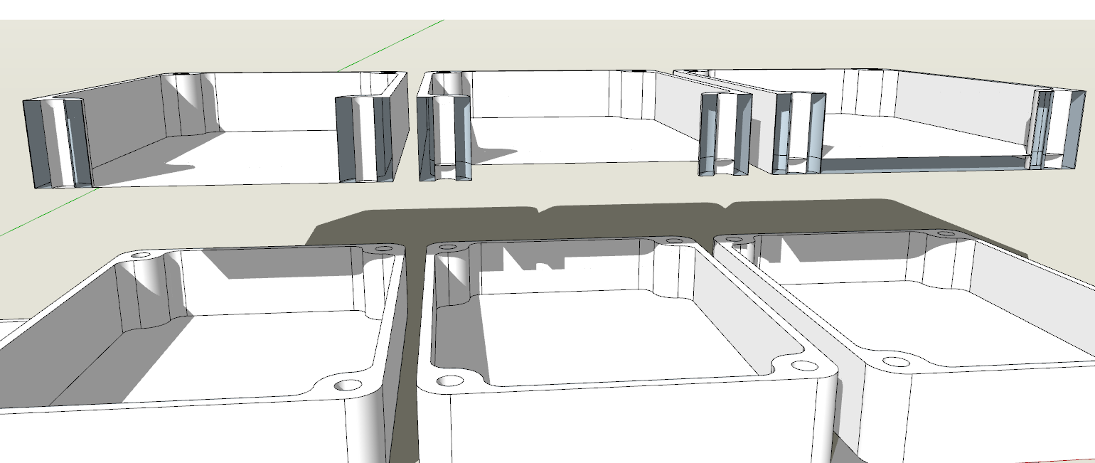
Then they start extruding with Push/Pull. Below I’m showing the results of simply pulling the wall of the box up. There’s a section cut above and an inverted copy below so you can see what the geometry looks like.
Note that the bottom of the box and the bottoms of the holes have no thickness. If you just use Push/Pull on those areas the faces only move. There’s no thickness added. You can use Ctrl (Option on Mac) to toggle creating a new starting face which will create the thickness but it results in a bunch of internal faces. None of these are 3D printable, then, without doing something to clean up the model. Here’s a closer view of the sections.
In simple terms this is the result of not thinking 3D early enough in the modeling process.
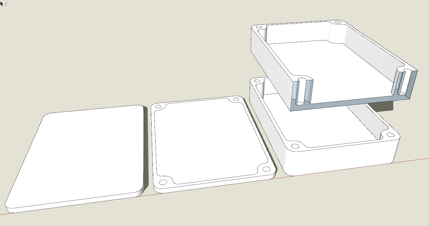
A better approach that almost always yields a solid 3D printable object without any cleanup starts by creating the outer perimeter of the shape and extruding it to the thickness of the bottom before adding the features that occur above the height of the bottom.
Basically don’t add features until you come to them as you build the height of the object. If there are features on the bottom of the object that don’t go through, get the object 3D before adding those.
In this case the hole goes through the entire part so it can be added to the 2D shape. Just remember to delete the face before extruding.
Next I extruded the shape to the thickness of the flange on the rounded corner before I detailed the inner shape of the flange. I also added the grid pattern on the bottom face at this stage because the recesses in the grid are the same depth as the flange.
The bottom face was extruded to leave the flange and the bottoms of the squares of the grid. The top face was extruded to the bottom of the recesses on top.
The grid was added to the top face.
The top face was then pulled up to the final thickness of the part.
Again, no cleanup was required. Nothing to prevent the components from being considered a solid. Now this thing is ready for the slicer and printer if I can get the ABS to stick to the bed and not warp.
Thanks Aaron. Yes, painters tape and glue stick. I wish there were threaded holes in the build plate. I could use small step clamps to hold the raft down.
i also played with Aquanet… for super stuborn prints, I ended up using a slurry of old ABS and acetone… I kept it in a glass jar and would brush a thin layer over the tapbe before prints… that really stuck the raft to the tape!
I do remember pulling my hair out for a while… I woudl get two or three great prints, then all of a sudden, NOTHING woudl stick to the plate! ABS slurry ended up working almost all the time, but it stinks and its a bit messy, but man, it was as close to 100% as I could get!
What is the size of the build plate? Mine is 230X150mm. I use precut build plate tape that has an adhesive to attach it to the build plate. I have had no issues with any filaments not sticking using only the glue stick.
Yeah, this post is going to my list of “posts that are useful to keep in a corner if a student don’t understand what I’m saying”
I feel the issue also depends on where people come from.
If they come from a 2d CAD software, 90% of the time they’ll struggle. I’ve observed that people coming from a 3d or more “hands on” background understand better the idea of sketching the minimum in 2d then detailing stuff in 3d. it’s more like sculpting and reacting live to the result than a very precise planning.
Ok, a few years ago (■■■■, 8?) I saw a guy in a fablab printing on an ipad screen.
He had a dead ipad, and extracted the glass sheet and used it to print on. It’s tempered glass, but still flexible (to a point)
I had to dig a bit, but here is an article about it.
Using an iPad’s screen (only about $15 on eBay), means you can hack and jab at the print bed all you want without fear of breaking it – It even has a bit of flex to it to help pry your parts off. Did we mention it also has a very uniform flatness, good thermal conductivity, and resistant to pretty much all solvents?
+1 to Aaron’s ABS slurry, it’s a pain to work with, (means cleaning the plate more often, tends to dry out, even in a closed container, and whatever you use to apply it gunks up…) but it really glues an ABS print to the plate.