Is there an extension in Sketchup for modeling rack and pinion geating using my Make 2017 version?
1 Like
Racks and pinions aren’t terribly difficult to model in SketchUp without any special extension. There is an old extension called SPGears that might help you if you need it. I don’t know that I’ve seen any extensions that would model a rack but you could take a tooth from a gear and create a linear array with it. There’s also Tax Engineering from Sketchucation and the Extension Warehouse that will model spur gears.
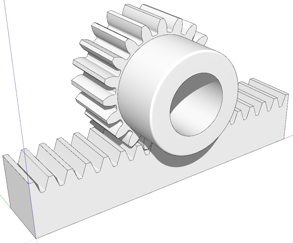
There’s plenty of information freely available on the internet from which you can model your own racks and pinions. I gleaned dimensions from McMaster-Carr’s site for this.
1 Like
You can try this plugin:
jimhami42_rack_and_pinion.rbz (3.7 KB)
It will allow you to create a rack or a pinion or both. The gears are suitable for 3D printing.
4 Likes
This link yielded a “NOT FOUND” response. wrong number, address unknown
What link?
jimhami42 sent a plug in…I guess that I don’t know how to use it. ![]()
I looked “SPGears” up and realized that there were lots of negative comments, so since I’m wanting to learn to design/model rack and pinion gears, I decised to try another site…haven’t found one yet. Any suggestions?
If you want to learn to design them, I would recommend what Dave said and try modeling them yourself. They are pretty basic geometry.
2 Likes
I didn’t see any negative comments that would indicate the extension shouldn’t be used. Some users made remarks that helped the author make improvements.
Since you want to learn how to model them, an extension is not what you need. Both rack and pinion can be modeled entirely with native tools. The model I showed was done with no extensions.
Jim’s extension needs to be installed with the Extension Manager before it can be used.
2 Likes
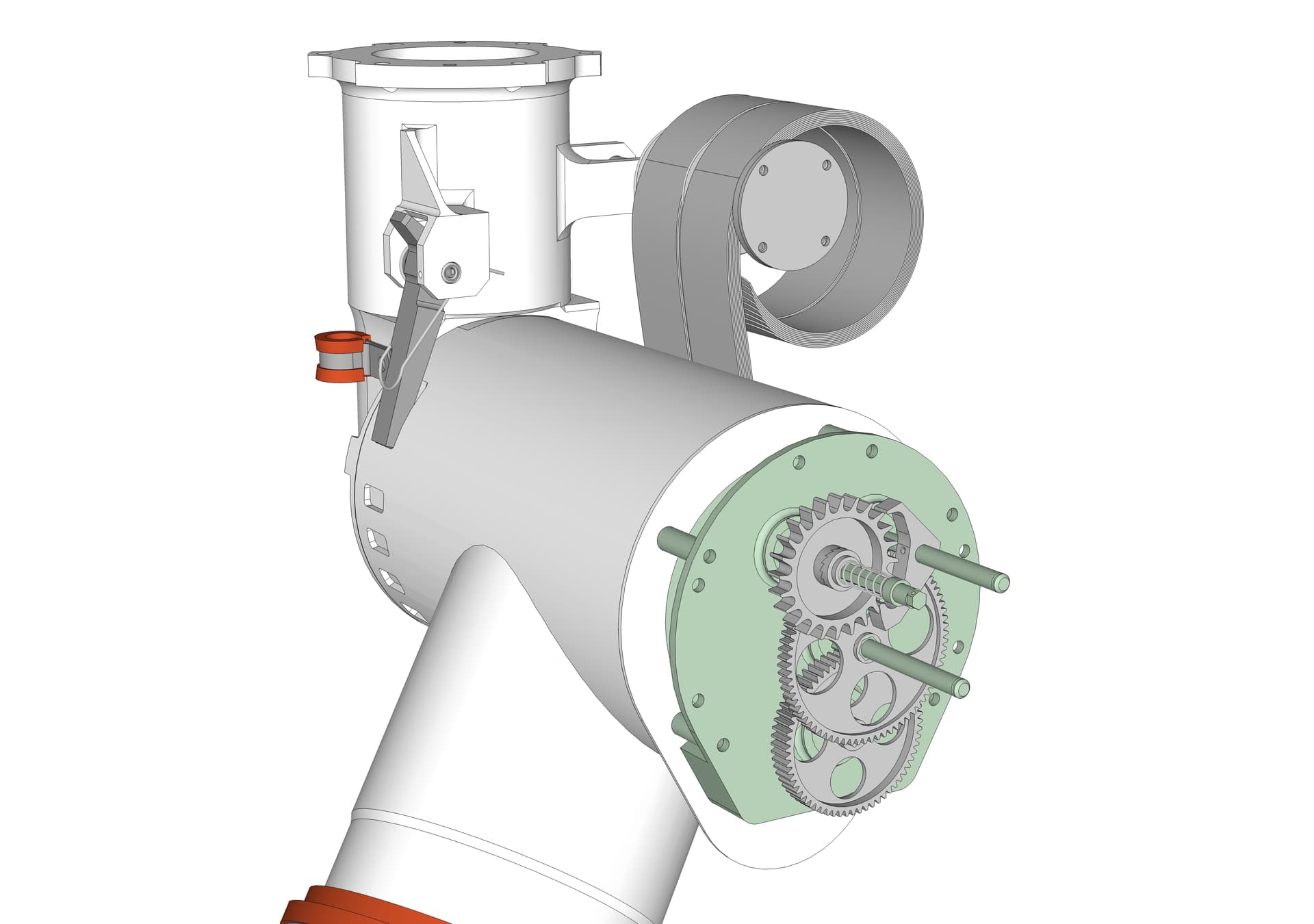
I concur about using SketchUp’s native features to model typical gears. Here is another example, something I made a couple of years ago. If you look closely at the teeth on the upper-most “gear” you will see it is not actually a gear, it is a wheel for an escapement. The point is that it’s straightforward to model “gears” with all manners of asymmetric teeth or other variations. There is also a small ratchet with angled teeth at the hub of the escapement wheel (the teeth are not very visible as seen here when the ratchet is closed).
1 Like

If you install the plugin, you can create true involute gears and a mating rack to go with it. As has been pointed out, you can also create them using only native tools, but you specifically asked for an extension.
2 Likes
Here is something that may be of interest. It is Matthias Wandell’s Gear Template Generator.

You’ll notice one of the export options is to a .SKP file
2 Likes
Works a treat… however, you might need to fork out a few shekels for this worthy product…
I use it extensively and it’s well worth the cost.
Not sure if you got your model figured out or not, but even if you have, this may help others in the future. Especially those having trouble wrapping their head around all the math involved in figuring out involute gears.
Initially, I was going to use an extension to build my rack and Pinion and even installed and tried one, but it was more confusing than helpful, and I wanted to get hands on and learn it my way, because as you can see, my pinion is a bit unique in this design.

I did some research on involute gears and how to model them, but there’s almost nothing out there for modelling proper involute gears in Sketchup (just those few extensions I wasn’t interested in), and the math to calculate seemed too complicated for me (math is my kryptonite).
Although, the video below helped me understand enough of the concept to move forward, and made me understand that the rack is actually stupid simple. There’s no involution or anything to the rack, it’s just basically a round cornered triangle. The only important thing, is the angle of the face where the teeth mesh. I went with 20°, as that seems to be the most common and recommended.

Just to note, with every earlier attempts to create a rack and pinion, I made the mistake of over complicating and over thinking the rack.
Anyways, the trick was working with only two components, which were half a tooth from the pinion and half tooth from the rack, which were aligned along the pitch line, or pitch radius, For the pinion, I first drew a circle and cut an 18° slice of pie out of it, which is half of 36°. A full tooth is 36° in my design, because I have 10 teeth.

It’s worth noting that the circle I started with was a 30 segment circle, which meant 3 segments per tooth. This just made it easier to work with and align things, but it’s not entirely necessary.
Next was to mirrored the half tooth component, for both pinion and rack and then combine those into a full tooth component. With the pinion gear, I rotate-copied that tooth component ten times at 36° to make a full gear. Mind you, it won’t look like a gear yet. Just a circle cut up into delicious slices of pie (I am becoming aware that I am very hungry for pie right now).

Now, to make my math easier, my Pinion’s circumference is exactly 500mm at the pitch radius, so the radius winds up being a bit of an ugly number (79.5775mm), but the advantage here is that 2 full rotations result in 1 linear meter of travel, and that made it a bit easier to model this next part as well… It’s worth mentioning that the reason I went with the constant circumference like this, was to actually make it easier to precisely control position with my microcontroller programming.
Next, because I know how far the gear will travel with a full rotation, I can divide that up nicely. Because I have 10 teeth, that’s 50mm of travel per tooth, or it’s also 36° of rotation for every 50mm of travel. This was fairly easy math and allowed me to map out the gear’s linear progression. I went with 3.125mm steps, so that’s 16 total steps. Each step is also 2.25° degrees of rotation (36° ÷ 16 steps), so at each step, I rotated the instance of my pinion component.
In the image below, all the individual gear component instances are visible, which might start to give you an idea of how this will work:

Now we put each individual gear component instance on it’s own visibility layer, organizing and naming them in whichever way works best for our workflow. These are the layers I used, and it’s nice because they’re in order, which makes the next steps a bit easier:

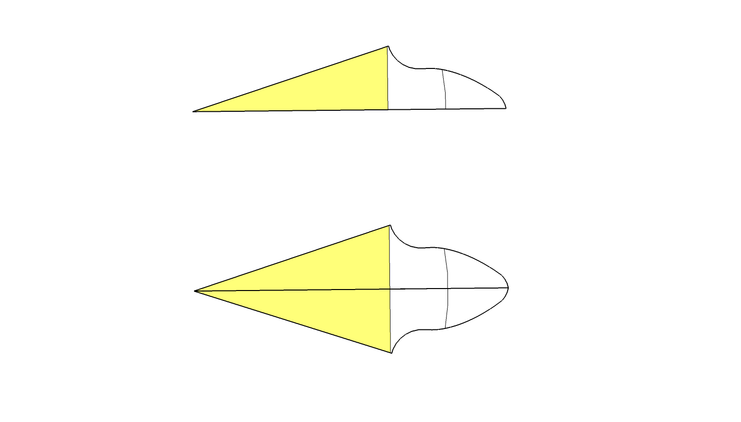
With all this set up, it’s best to refine the rack’s tooth profile now. Like I said, it’s stupid simple because the rack is not involute, and the rounding radius is mostly arbitrary. I just rounded the rack tooth using nice clean numbers that were easy to sketch and looked right.
With that set up, the rest was pretty simple, I would just toggle the layers to simulate the gear rotating along the rack, and at each step in it’s linear progression, I would go into a half-tooth component on the pinion, anywhere it was conflicting with the rack, and then just draw out the edge of the rack tooth. I kept going through all of my layers like this, re-entering the component anywhere it conflicted, until I wound up with something that looked like this:

Then, I simply delete the excess lines and faces, then run through the layer progression again to make sure I’ve cleared out all the conflicts. I actually used Scenes and animation so that I could watch the gear rolling over the teeth for a better feel of how well it worked, but this was a very annoying and clunky experience, so I think I’ll use Fredo6 Animator for this part next time.
I avoided worrying about creating clearance here, by the way. The teeth at this stage mesh with perfect tightness. It wasn’t until I was happy with the profile and ready to start extruding that I used the offset tool to create my clearance on the 2D shape.
Just for the record, I’m a hobbyist, and this is the way I did it, so I’m not saying it’s the right way. However, I do feel confident enough in this method that I wouldn’t hesitate to send this out for CNC or 3D printing on my own project.
1 Like