I am trying to create an object that will serve as a “connector” for two other objects. Specifically, I want to attach one type of whistle to another type of whistle. I have already printed the individual whistles and glued them to each other, but I think the design would look better if there were an object that connects the top whistle to the bottom whistle, so as to make the two whistles seem more like one object.
I envision the “connector” object to be basically a small cube that rests upon the top of the bottom whistle. The side of the cube that faces the top whistle will be perfectly shaped to fit the contour of the top whistle (as you can see, it is curved and there is a small triangle shape there as well).
As a beginner, I have no idea how to create this object in Google SketchUp so that I can print it. Any help or advice would be greatly appreciated!
As a gentle poke, please be aware that Google sold SketchUp to Trimble about four years ago and has no further involvement with the product.
Since you have 3D printed the whistles and glued them together, I assume you have modeled them as Groups or Components in SketchUp. If not, you should do that now since otherwise geometry will “stick together” wherever it touches, and that will make editing the model harder.
Next you should scale the model up by a factor of 10 or maybe 100 (no hard and fast rule, you have to try it and see how big a factor works). After your manipulations, scale the model back down to the original size. If the whistles are Components, this sequence is easiest by making copies, scaling the copies, doing your edits on the copies and then simply deleting them when completed. The unscaled originals will remain, with all your edits at the original scale. These steps are needed because some SketchUp operations are not able to create small faces and edges, which will leave holes and missing parts if you work too small.
The easiest way to do the actual operations depends on whether you have Make or Pro. There is nothing that Pro does that you can’t replicate in Make, but Pro’s solid tools can make operations simpler.
You need to study up on SketchUp’s Intersect Faces With… command. There are a great many topics on this forum showing how to use it. There are also help pages in the SketchUp help and tutorials in the YouTube suite. As a newcomer to SketchUp I think it would be a good idea for you to figure out how to find these resources rather than having us point you at them - but if you try and can’t find them or can’t understand, come back here for detailed help.
As a final note, you will receive much more detailed and explicit help if you can upload your skp file to the forum (click the seventh icon from left at the top of the reply window to select a file for upload).
(Uploading as a zip because the file by itself was too large)
I feel like what I did is super messy, but can I get it to a stage where it’s printable? When I print, I just want to print the “connector” so I will delete the two whistles before printing.
I used an extension to import them into SketchUp (they are stl files).
I don’t really care about the actual whistles though, as I already have them printed. I just need to make a “connector” piece and then delete the whistles and print that “connector” piece, if that makes sense.
Don´t know when that happened, but the upper whistle is not printable because its backfaces are outside.
You must turn inside out. (sorry, don´t know the english word für “umdrehen” in SU).
No good picture because I changed the faces. Yours is showing that.
BTW: the connector should not be solid if You don´t want to cut of the part for the “necklace”.<img
A screenshot in netfabb shows, that the upper whistle has to be inverted:
I don’t need to print the upper whistle because I already have it printed. I simply need to create the connector object then delete the two whistles and print just the connector object.
Also, I believe the connector object I have created does not cut off the “necklace”, I tried to make it specifically so that it doesn’t.
My question would be is the connector object I created “good” enough to print? I don’t know how to get it to be all one object because I created it somewhat clumsily out of many different rectangles and such. So basically I don’t know if it’s even printable, or how I would get it to be printable.
As first thought consider using solid tool ( or Boolean ) to cut the profiles of the two items such as they will fit (nicely) You probably want the skp files to do that but question if that is your original effort plus not clear from you profile if you have the PRO version or the make version of SU?
Import the item(s) into SU and give use some good skp files to work with.
What exactly do you mean by cutting the profiles of the two items such as they will fit nicely? Also, can you point out exactly what is wrong with what I have currently done and why it can’t be printed?
Here are the two skp files with the original whistle models (in one zip):
< I am not in that type of business. The whole point is learning and you will not do that if effort is done for you.
Attached is the top solid model, compare that to what you have been doing. Caution: I do not consider this acceptable for you FDM PLA printer even though it is reported by SU as solid. The are over hangs that may sag by the use of melted plastic. It’s more suited to SLA where in its self supporting. There many many write ups on the various print technology mostly by the commercial printers. Check their web sites. That is one of the decisions one needs to make at the start of you design process.
After you have the other model post your model with the way you want to arrange them so some one can show to strengthen the total model. whistle_0507_2016_2300_2014.skp (2.5 MB)
I appreciate this clean skp file of the top whistle, but my problem is not with the whistles. I need to create a “connector” object. Essentially all I want to do is create a hollow rectangle that has one face curved, so as to fit against the contour of the top whistle. I tried to do this as I showed earlier but I think I was unsuccessful, as it seems very unclean to me. If you could point me in the right direction as to the tools and process I should use to get to my goal it would be much appreciated.
Neither of the whistles in the zip file you refer to are solid and need to be if you have printed them. If you have the solid versions, use them, make the connector a solid. Use the solid tools you have to perform Boolean operation to get the connection profiles you need.
BTW you have never answered the question if you have PRO or make version of SU. Your profile seems to imply you have PRO. That info is needed if folks are going to help you.
If you have free then you will have to do an intersection. Since you have the whistles already printed you can just print the connector and then bond them.
Not wanting to point out the obvious but…
If you use a copy of both whistles positioned as you want them, then draw a cube or whatever shape you want to join them between the two, then explode everything, then select everything and right click and choose ‘Intersect faces with selection’ .
Now all you need to do is remove the parts that are the whistles. Leaving only the parts that make the connector.
@mac7595 I don’t have the solid versions of these objects. I printed them directly from the stl files on thingiverse, but when I imported the stl files into sketchup, they were not solid objects and I don’t know why. How did you make the top whistle a nice solid object?
I do have the PRO version of SU.
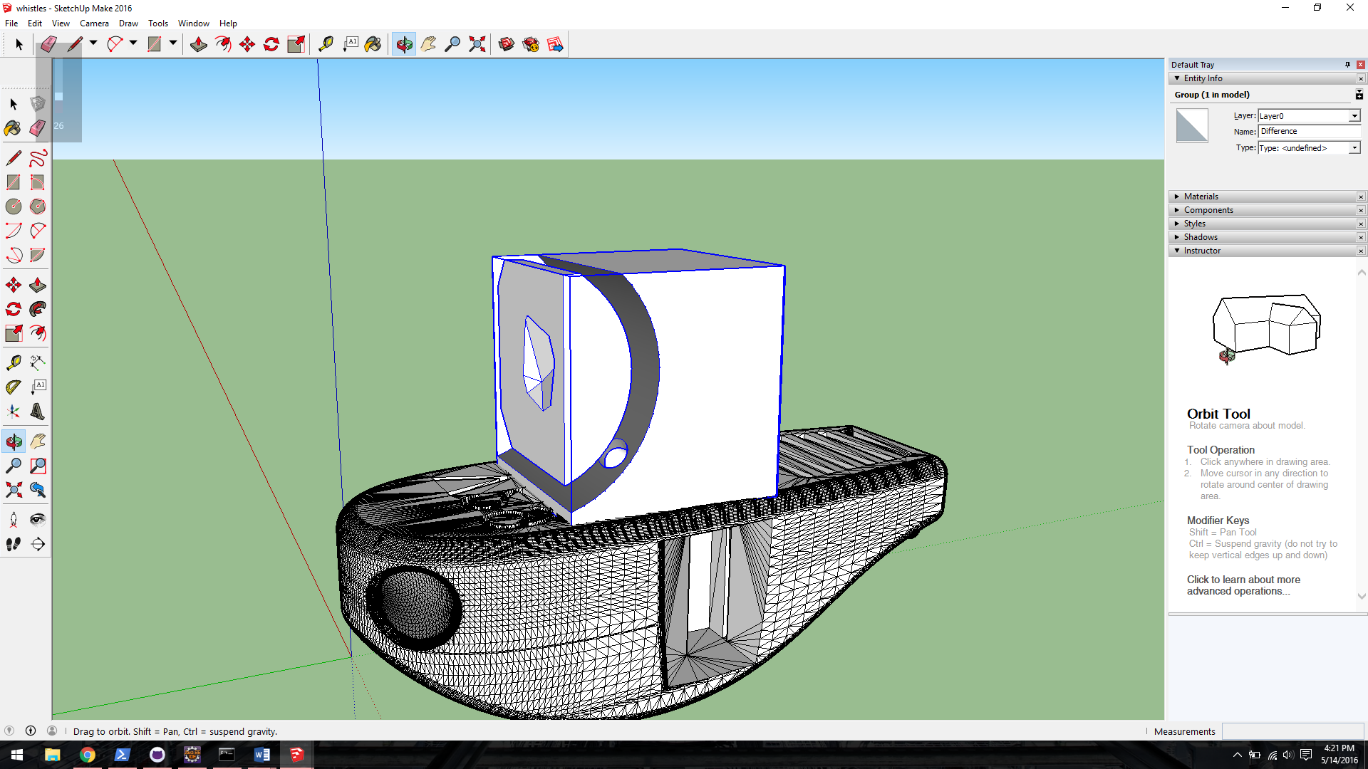
@Box What you say makes a lot of since so I tried to do this but I seem to not be able to make a solid cube (I drew a rectangle then used push/pull tool to make it a cube but this doesn’t seem to make it a solid?). Also SU says that the whistle isn’t solid. Both the whistle and the cube would need to be solid for me to use some solid tools to make the object that I want. See the image below:
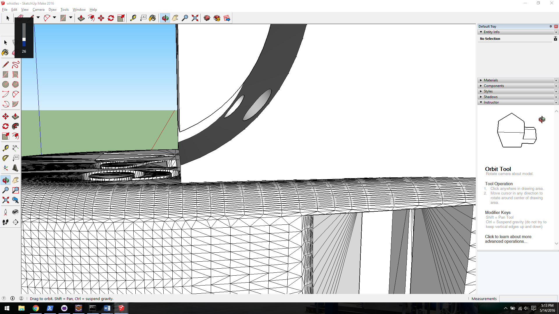
When I use the subtract tool, the result seems to treat the whistle as being “hollow” which is not what I want. I would like the parts of the whistle that intersect the cube to be cut entirely from the cube, but that is not what is happening. See below:
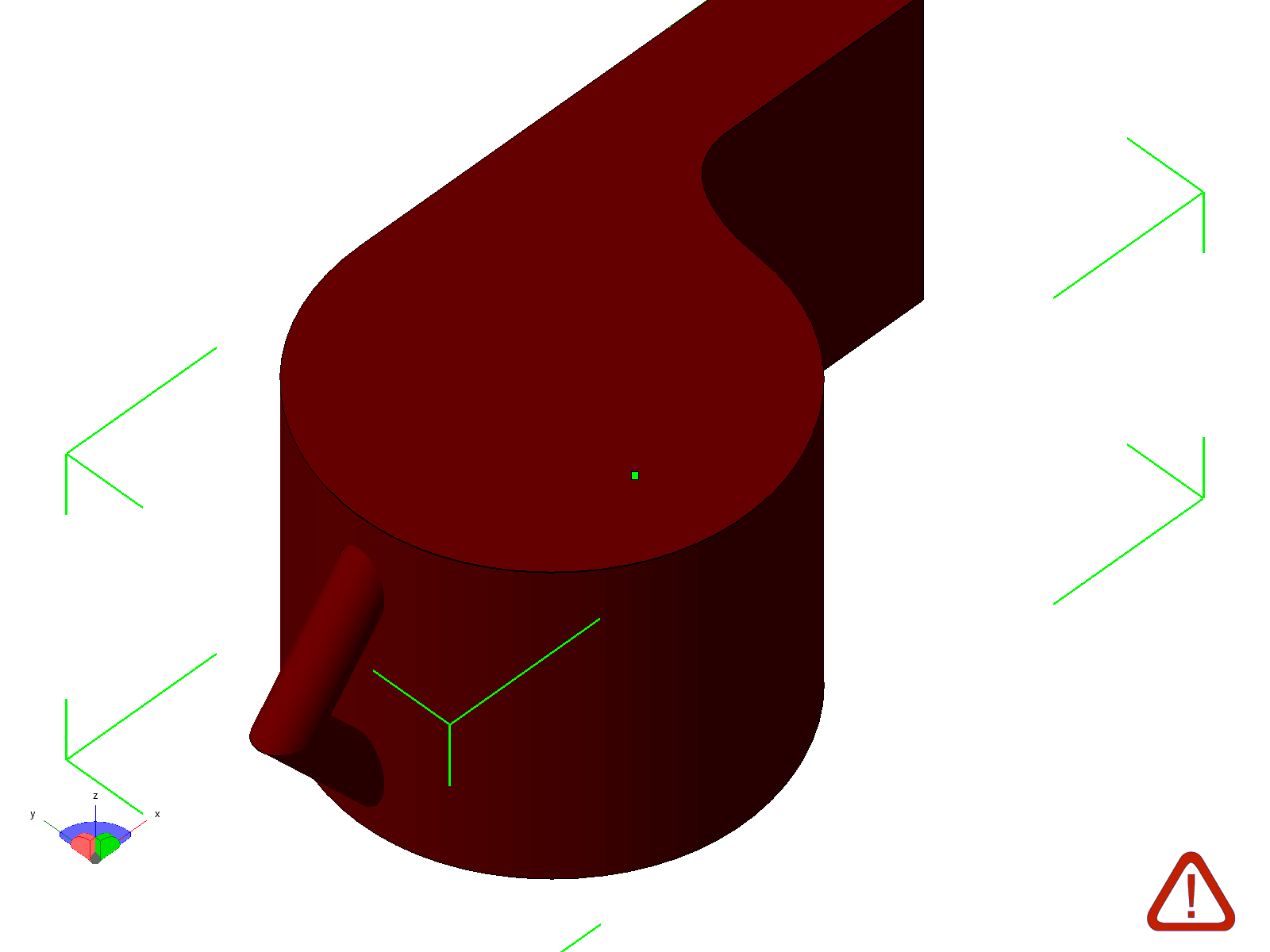
I actually realized that part of what I want to delete is the space encapsulated in the “tail” of the whistle. The subtraction tool just gets rid of the outline of the tail, but not the space of the inner part of the tail. How should I approach this?
Unless you get rid of the inner cavity in the mating part, you’re going to have that bit of the cube on the inside. It only take a couple of seconds to delete the unwanted geometry from within the cube group, though.
How should I go about deleting the unwanted geometry? It seems that I can’t remove individual parts from a grouped component. Also, I can’t use solid tools on the component anymore because it is now “locked” it seems.
Additionally, even if I were to remove the obvious geometry that I don’t want, I still have the portion that comprises the “tail of the whistle”. This tail makes an inlet of the tail into the cube, but I want the space between the tail to be removed as well. As of now, it just looks like there are holes in the cube. See below, does this make sense?