Have you learned how to edit groups, yet? I get the impression you’re trying to run when you haven’t even learned to crawl.
Open the group for editing and use the Eraser tool to eliminate the geometry you don’t want. If you need to fill in holes, probably the easiest thing would be to turn on Hidden Geometry and draw in the edges to skin over the hole. Erase the sides and bottom of the hole first.
This is all very basic SketchUp work to edit the cube group.
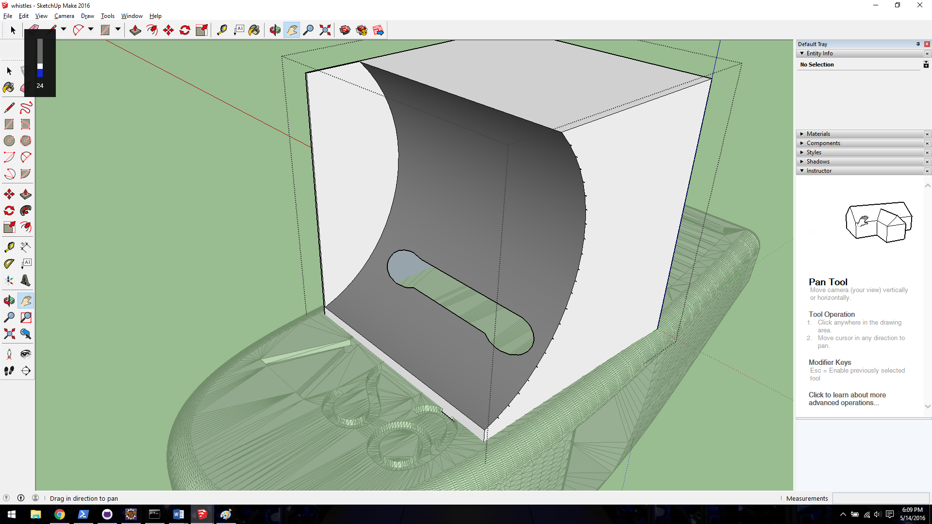
Alright, thank you! Now I want to get rid of just the small portion of the top face of the cube that is defined by an arc. I want it to match the other curved side of the cube that doesn’t have that thin slice of wall. How should I approach this? I tried drawing an arc and then erasing that part of the wall but it simply erases the entire wall. See below.
How did you get yourself into this in the first place?
Do you really just want a cube to go between the two whistles? Is the geometry for the lanyard on the top whistle going to be cut off so the cube shape can be mated to it? How big does the connector have to be?
I want the cube to be perfectly aligned to the contour of the whistle, so that is it curved and also has a hole in it for the lanyard part (I already printed the whistles and attached them, I don’t want to print it again). The connector should be around the height I have it at. I’m just trying to make these two whistles look like one object instead of two distinct objects attached to each other, if that makes sense.
I can’t find the correct orientation for the second whistle so it fits the curve on the cube. If you’re attaching the whistles together, the lanyard part isn’t going to be useful. Why not cut it off and save a bunch of aggravation.
Don’t take it the wrong way but the whistle models are awful.
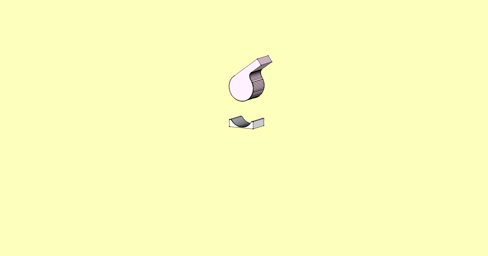
Simple case small retcangle intersected with top whistle assume you will print separately then bond two together. For convenience I removed the lanyard but you can do with what ever you want with that.
The back up shows made in 2013; functional and even decibel meter readings for them, has small spherical ball like real unit but it’s connected to wall.
BTW infamous911
if you intersect then the units do not need to be solid like when solid tools are used
infamous911: Thought I poasted this link but guess not How do I convert STL graphics to a solid model? | GrabCAD Questions;
If you read through the postings therein you will find reverse engineering from stl to su model is not best practice. A number of the edges you see in some of your models are a direct result of stl=> SU import… Most if not all can be removed by using the delect coplanar edges extension. The best approach would be to use the object models you have access to as shown in some of you post , make sure they are clean models. You will have to import them as dae. models since you do not have pro version’ Once you have imports to SU save them as component ( not same names as present ones you have because of next step)
The SU component browser has a quniue capability to substitute one component with another all you have do select the whistle component you have in your drawing, open component browser select the new one and then context to " replace selected". Be aware it copies into you model at scale and per axis you have set.
I have not done the “bottom” whistle steps but have good model of top model.
PM me if you want try top and I’ll send to you.