I have been working on a component for one of my cars (which I will be 3D printing). It consists of several different pieces that I designed separately and then merged into a single object. All-in-all, each piece printed well as stand-alones. But when I brought them all together, I’ve got holes!
FYI: I am developing in meters and then reducing the size to mm in my slicer.
I know my failure is in the fact that these separate pieces were able to print even through they were not solids. I’ve been using Solid Inspector2 to aid my efforts but some of the items I just couldn’t figure out how to fix. Since the pieces printed okay…I just moved on. But now I’m taking a step back to learn and understand how to make each piece a legitimate solid before bringing them together again.
The first piece is the shell in which all pieces will ultimately reside. Using Follow Me, I am able to create the shape I want.
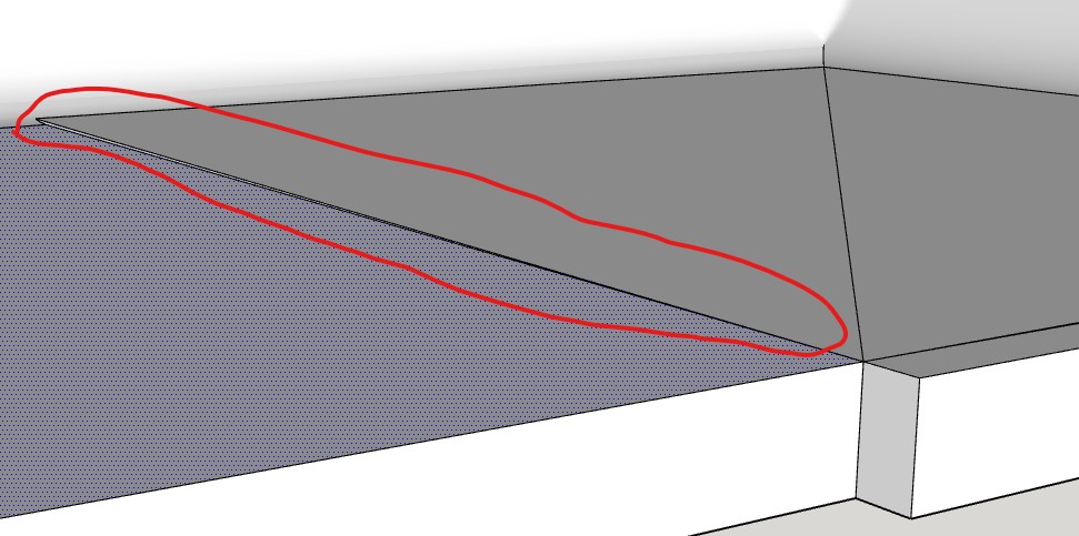
Through trial and error (and a LOT of luck), I’ve been able to address some of these problems…though I’m not exactly sure how or why since I’ve tried many things along the way. But, not matter what I do, I cannot fully enclose the inside corners of the shell:
Can anyone help me understand how to resolve these issues, and understand the best tools to use in the process?
Try using just this much of your profile. The upper horizontal line in your profile is not parallel to the green axis.
Scale it up 100x more, do your follow me, triple-click to select all, and run intersect selection. At that point, Solid Inspector will fix it. Delete the three small faces and two lines in the corners and add two lines to close the faces.
Not sure if the bottom curves should be parallel either? but with the better curve profile it will run the follow me Ok using just the part as CJ said, with a tiny cleanup.
Interesting…I got it to work following your advice. Intersect Selection was definitely the piece I was missing. Once I applied that, things just fell into place.
A couple things I noticed:
I did not have to scale up any further to make this work. I tried it as-is and 100x with same results.
It was a little trial and error for me to decide how long to make the horizontal leg. The curve is 7 radius so I started with that (measured from the front corner). That left a small sliver that wouldn’t join the bottom.
I ended up using 5 (which was the intersection of the small segment in the image above) and it worked great adding the bottom. Is there any rule-of-thumb for deciding this length when dealing with curves?
No matter how long of a horizontal leg I used, as long as it was smaller than the overall width of the object, the steps above worked and I got a solid. But what I noticed was that the bottom ended up with a ‘step’ when the leg got ‘too long’.
(This image was from an object created with a 34 length horizontal leg. I got the same results at 20.)
I believe this could be considered a defect because it appears the Follow Me object did not retain it’s proper orientation to the plane it was following…essentially, it tipped at the corners. Thoughts?
What an exciting exercise! Thanks for the assistance and guidance. I’m learning something new every day. Now I’ll move on to the next piece…
For my particular application, the inside of the arc would not need to be the same as the outside. This shell will fit within the console of a car so it is the outside that needs to fit.
For your solution of using a different curve profile, did you just try a couple until it worked? Or is there some calculation or methodology used to decide?
I don’t know if it’s a requirement for your shape, but the top of the “floor” line in your profile isn’t level so that creates an issue when follow me turns the corner and is following a level edge in the green direction. I found it was much easier to work with if the floor line of the profile is first made level (parallel to the green axis).
Otherwise I created a miter where the sloped floor meets the level floor.
EDIT Actually I’m not sure it “meets a level floor” but it is meeting a level direction-and not sure why FM doesn’t do the miter, but it may have to do with the path radius going to zero before that portion of the profile.
That is likely the problem from the start! I created guide lines so I never second guessed the size. I’ll recreate my shape again and double-check it’s location and measurements.
On things like that I’ve found it’s worth it to scale huge! It avoids tons of problems, and makes the clean-up much easier also.
But I’m glad you got it!
You should check out the Dave Method, it’s incredibly useful.
Ok, I recreated my shape and validated the measurements and positioning. Here is what I found:
There was still problems with surface borders and internal face edges with the longer horizontal legs. So I shortened the leg to a the edge of the inside arc (where is connected to the horizontal line across the top of the leg).
I did have to scale 100x to get it to work. At the as-is size, still could not get those inside corners to seal.
To sum it up, part of the problem was user error (leg not parallel and too long) and the other part was missing the Intersect Section step.