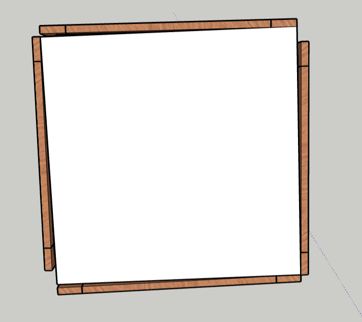
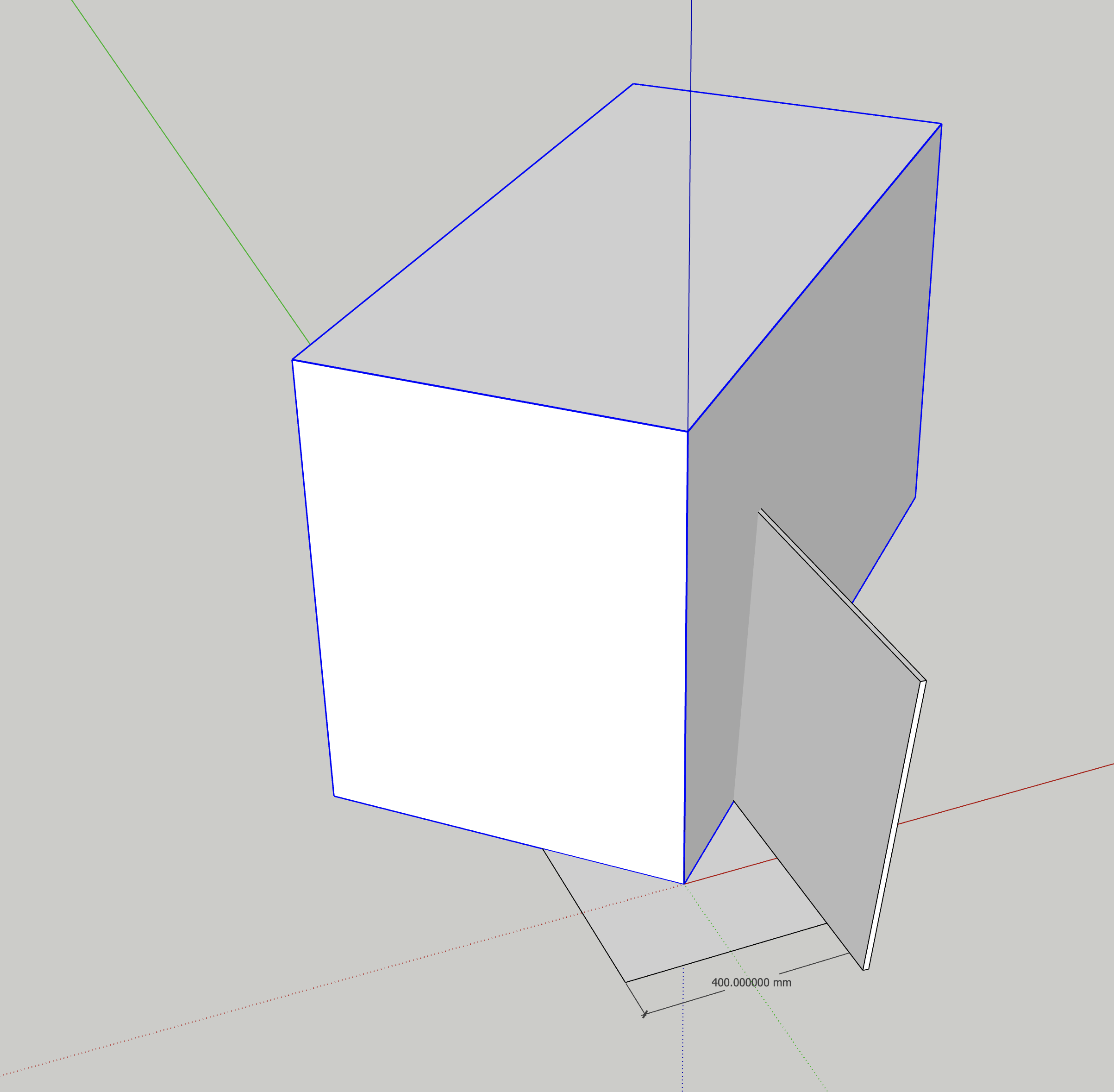
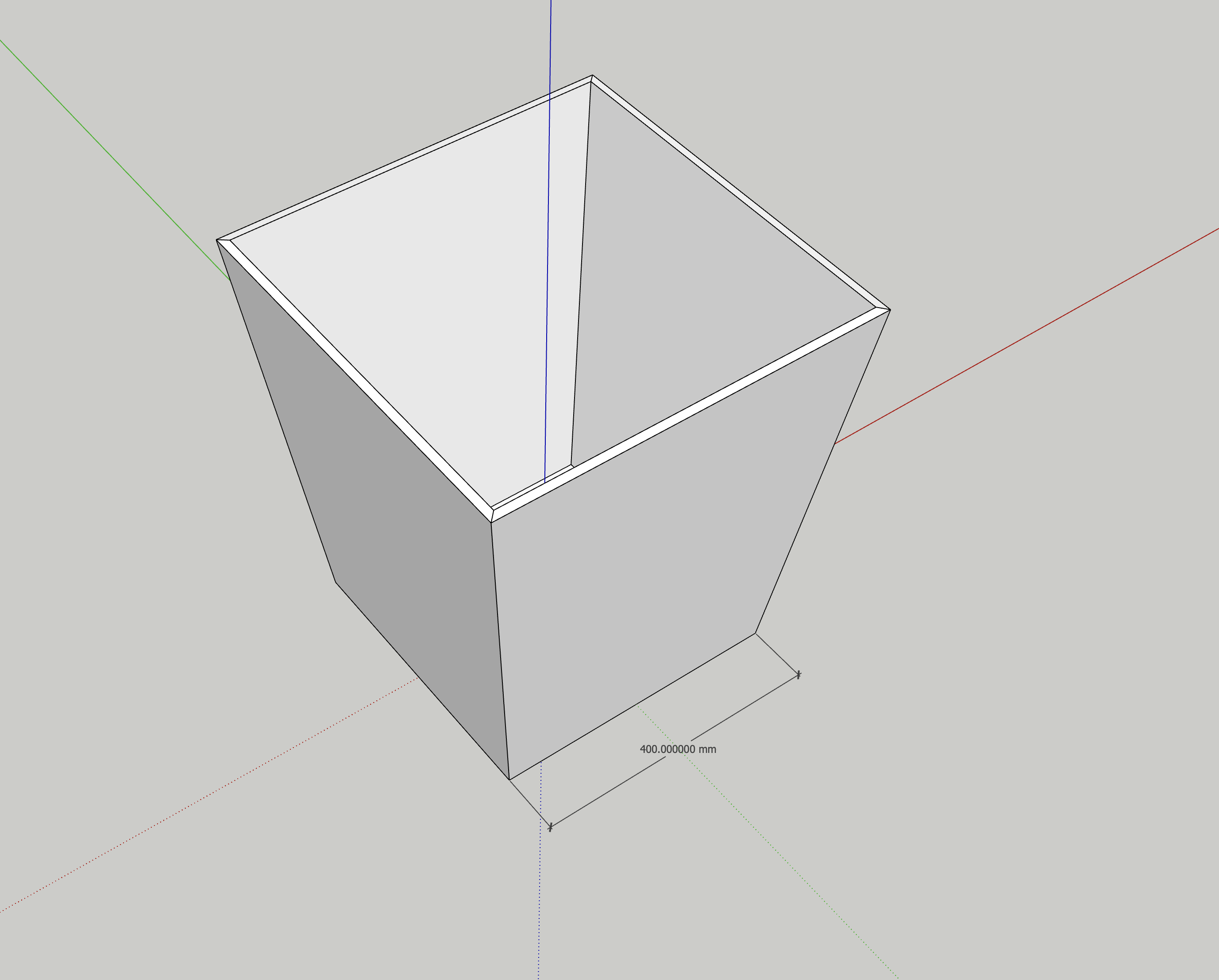
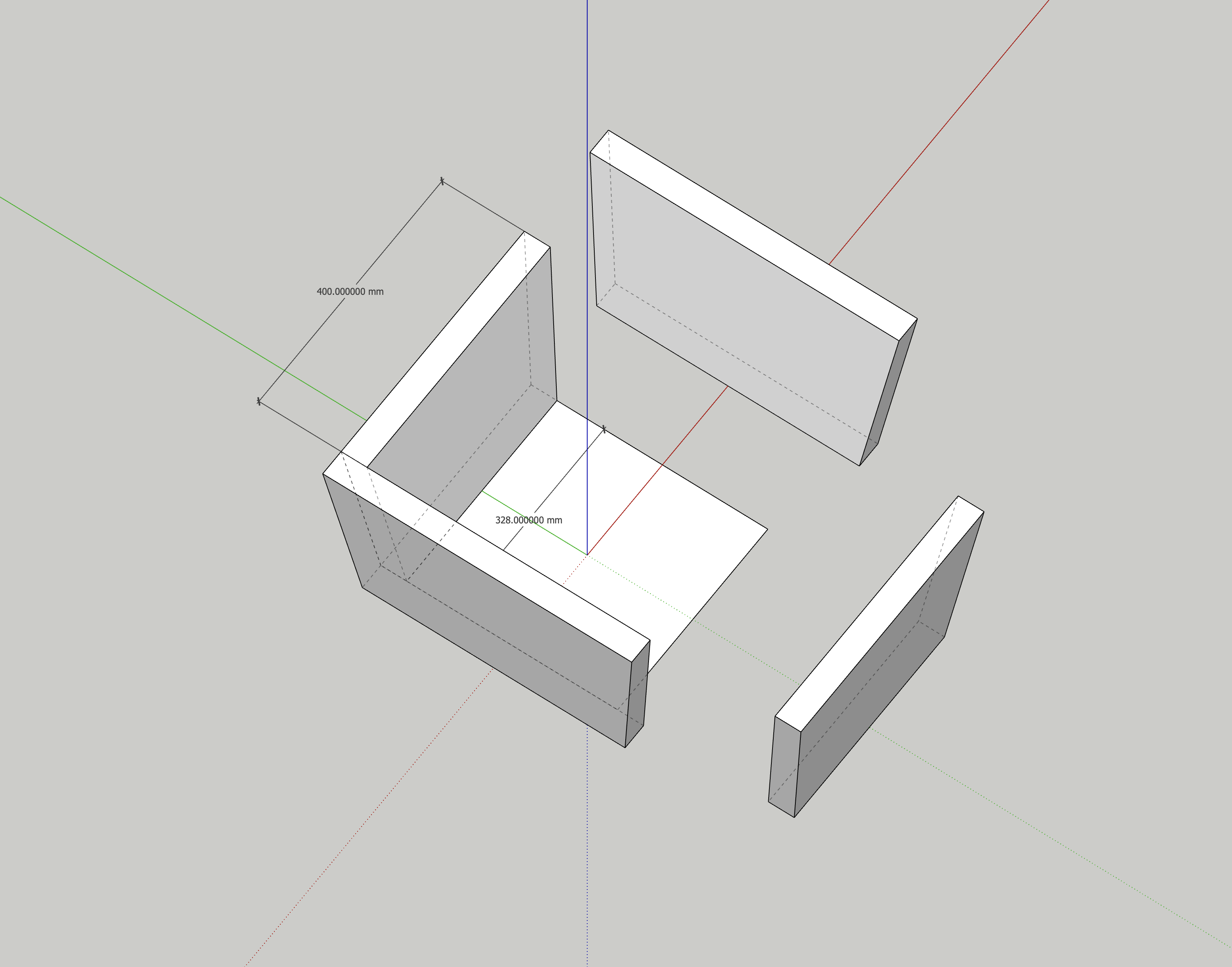
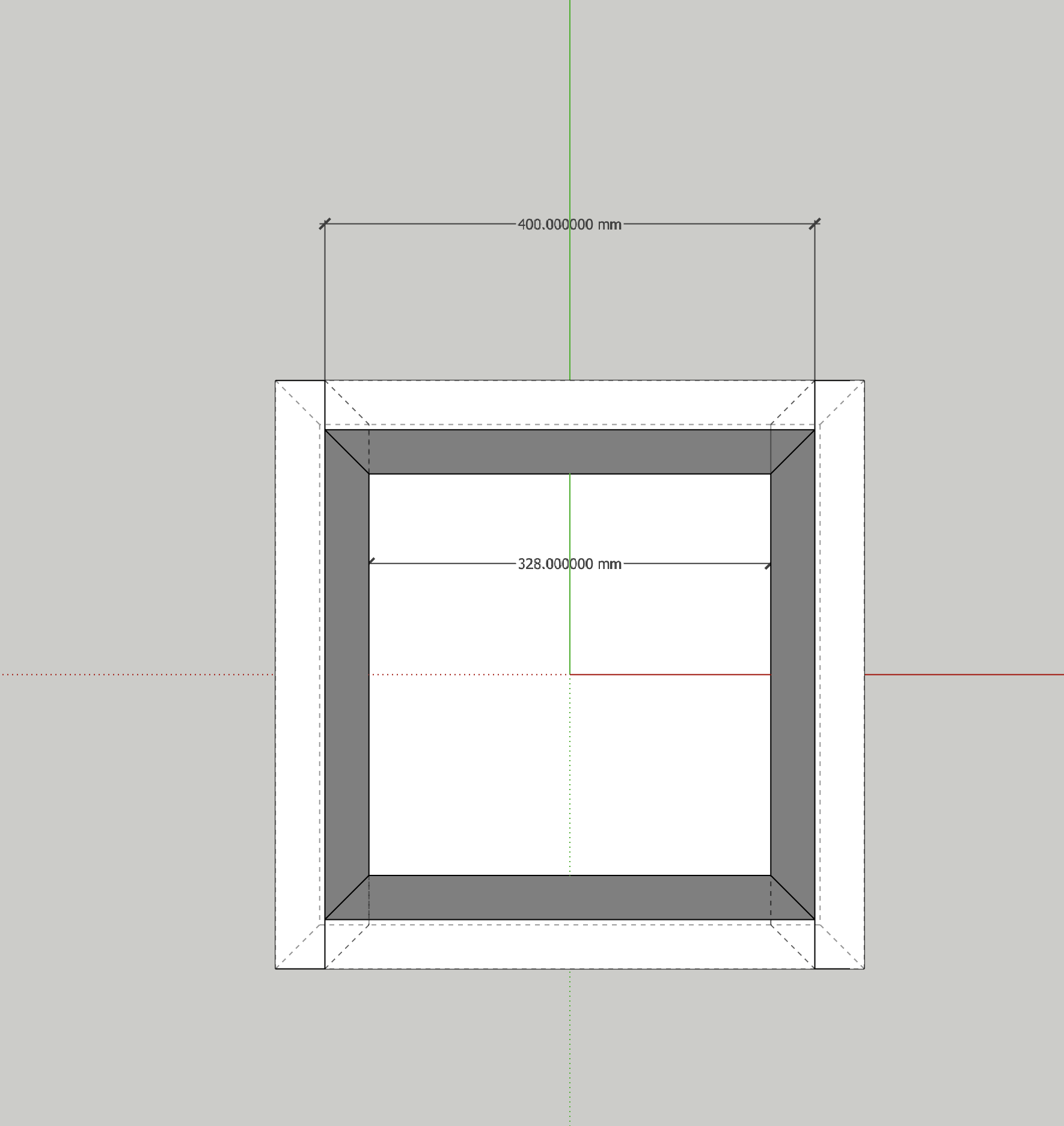
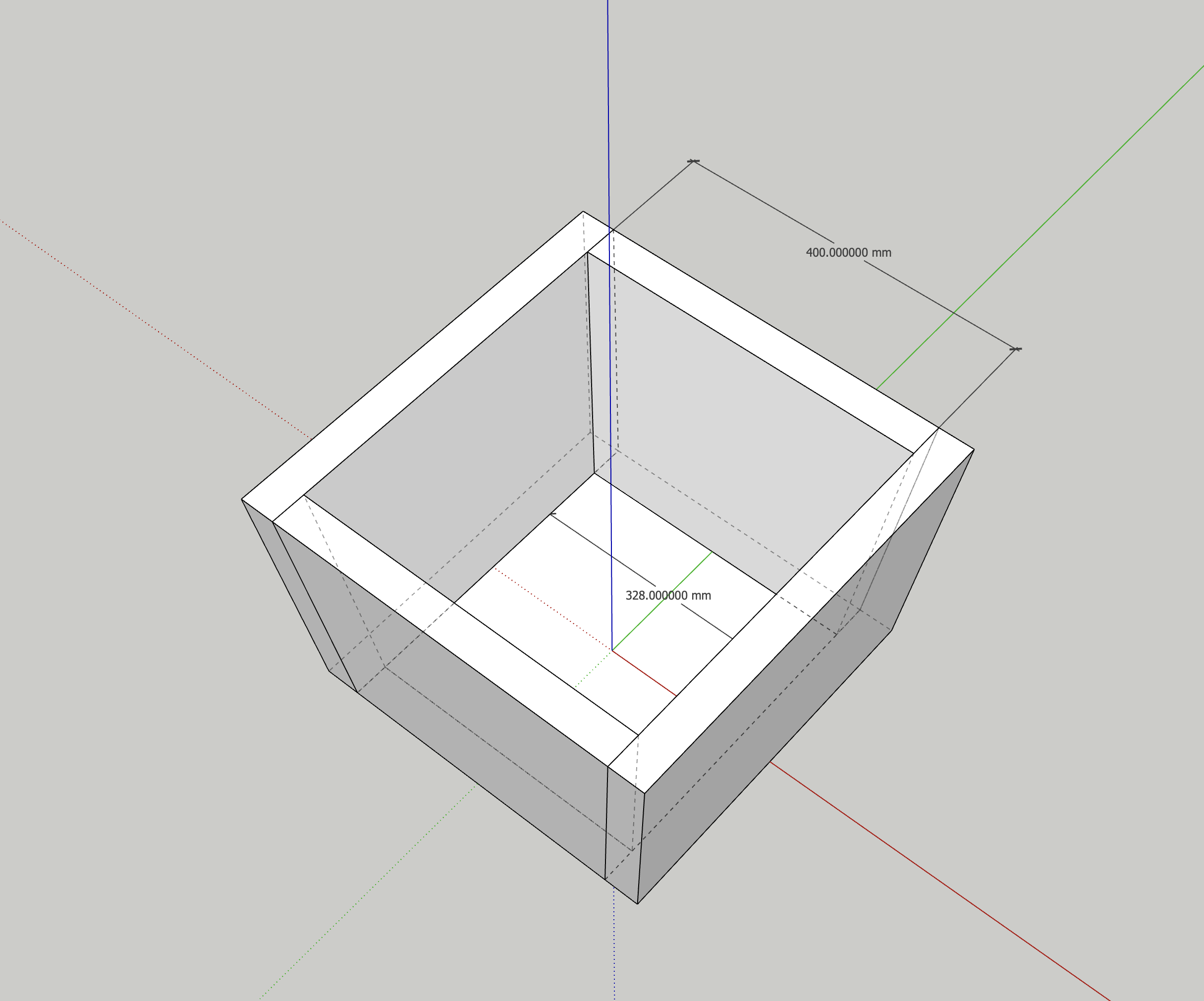
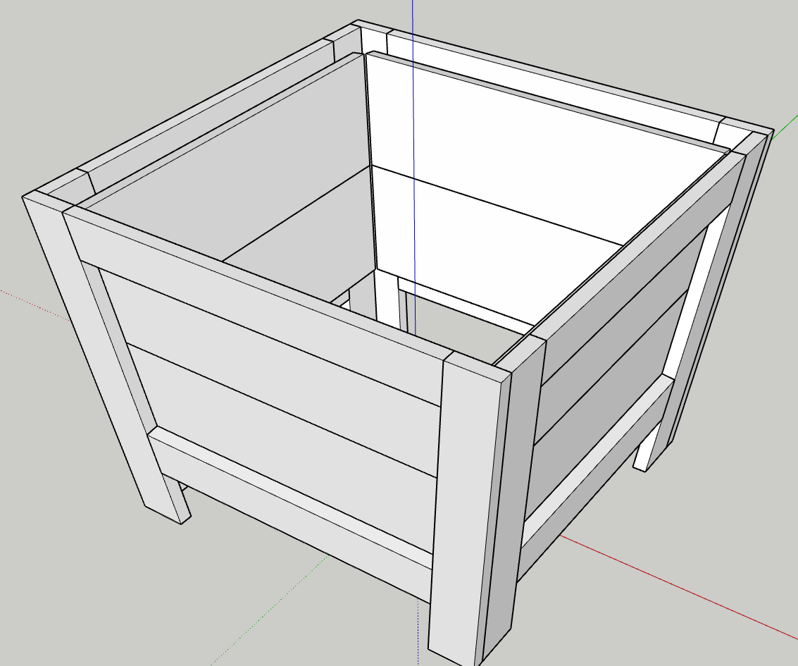
Im making a slanted planter box. It has a 7 degree taper outward, making the top larger than the bottom. When all the panels are at a 90 degree upright the corners are 90 degrees. I then slant the panels out by 7 degrees and as you can see in the screenshot, everything then becomes angled away from 90 degrees. The square in the middle is a reference 400mmx400mm. Im also unsure why the right panels is now shorter than the rest too. Im very puzzled and no idea how to fix this. Ive spent 4 days designing this over and over thinking its something im doing wrong in the design phase, and im frustrated.
If it makes any difference to how to correct this issue, I am using the free web version of SketchUp.
Im unable to attach screenshots to this reply, as im a new user. But the dimensions for my planter are as follows (before the 7 degree outward angle)
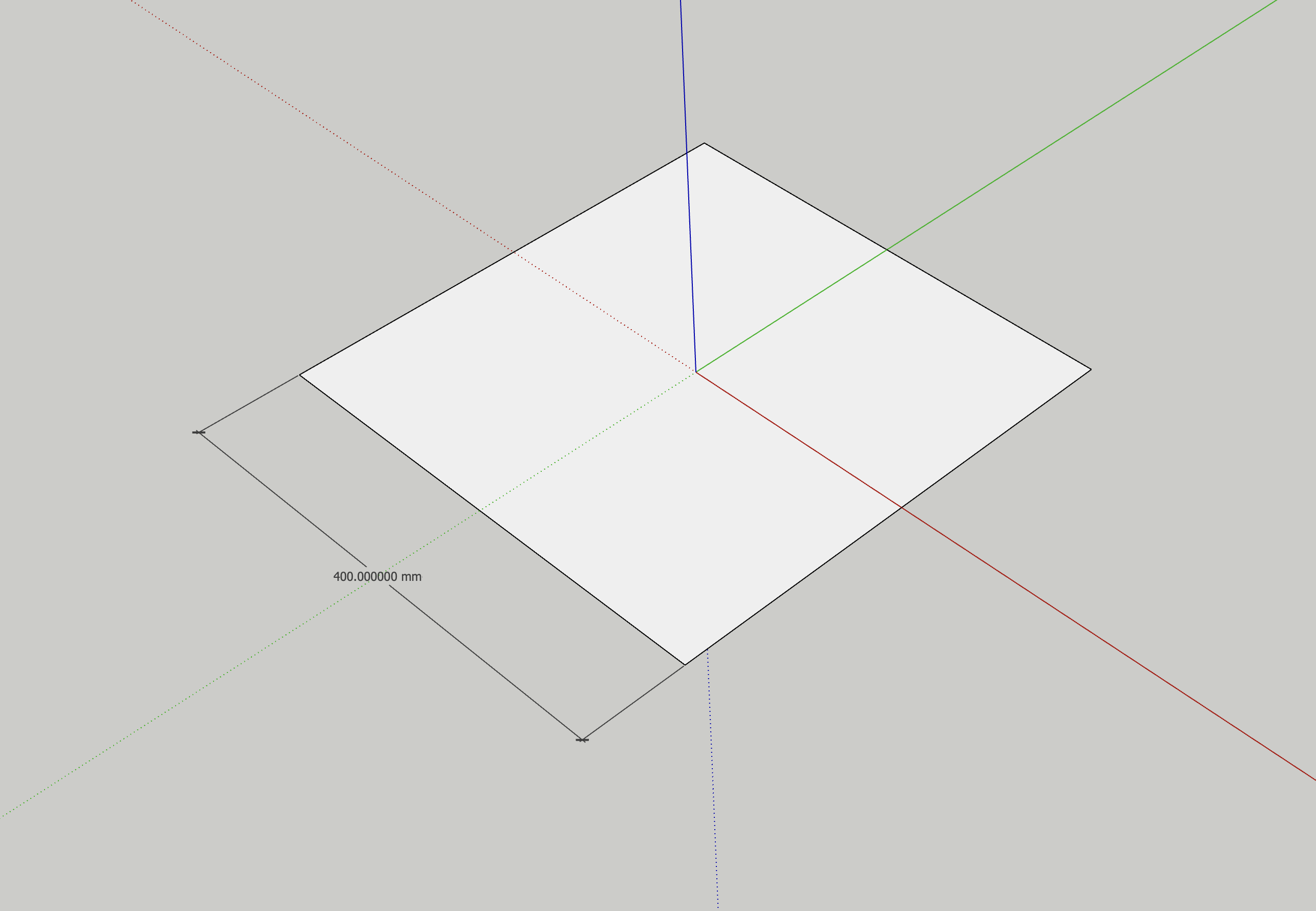
400mmx400mm top opening
328mmx328mm bottom (accounting for 7 degree taper)
4 x 40mm frame pieces (2x300mm sides cut with 7 degree angle, creating parralellogram.1x319mm top panel, 7 degree angle, creating trapezoid. 1x270mm panel, 7 degree angle, creating trapezoid. 2x102mm boards with 12mm inset, 7 degree angles to fit on the inside of the planter walls. All boards 12mm thick)
I do not have the ability to do miter cuts. I am doing butt joints.
The steps I took to get here:
Design 1 ‘Long’ Panel on 90 degree upright.
Duplicate and rotate 180.
Design 1 ‘Short’ Panel on 90 degree upright.
Duplicate and rotate 180.
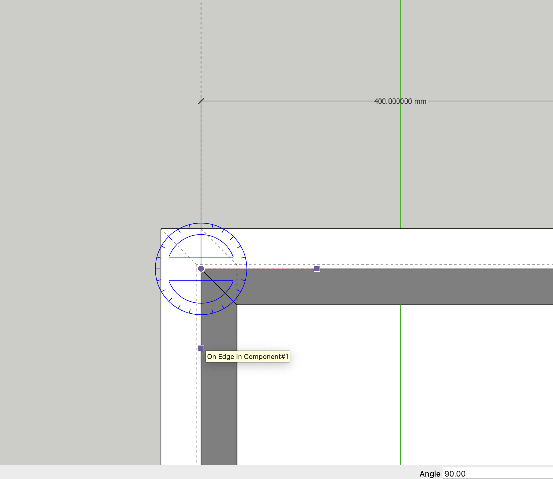
Using protractor tools, measure all 4 corners, ensuring 90 degree from one another.
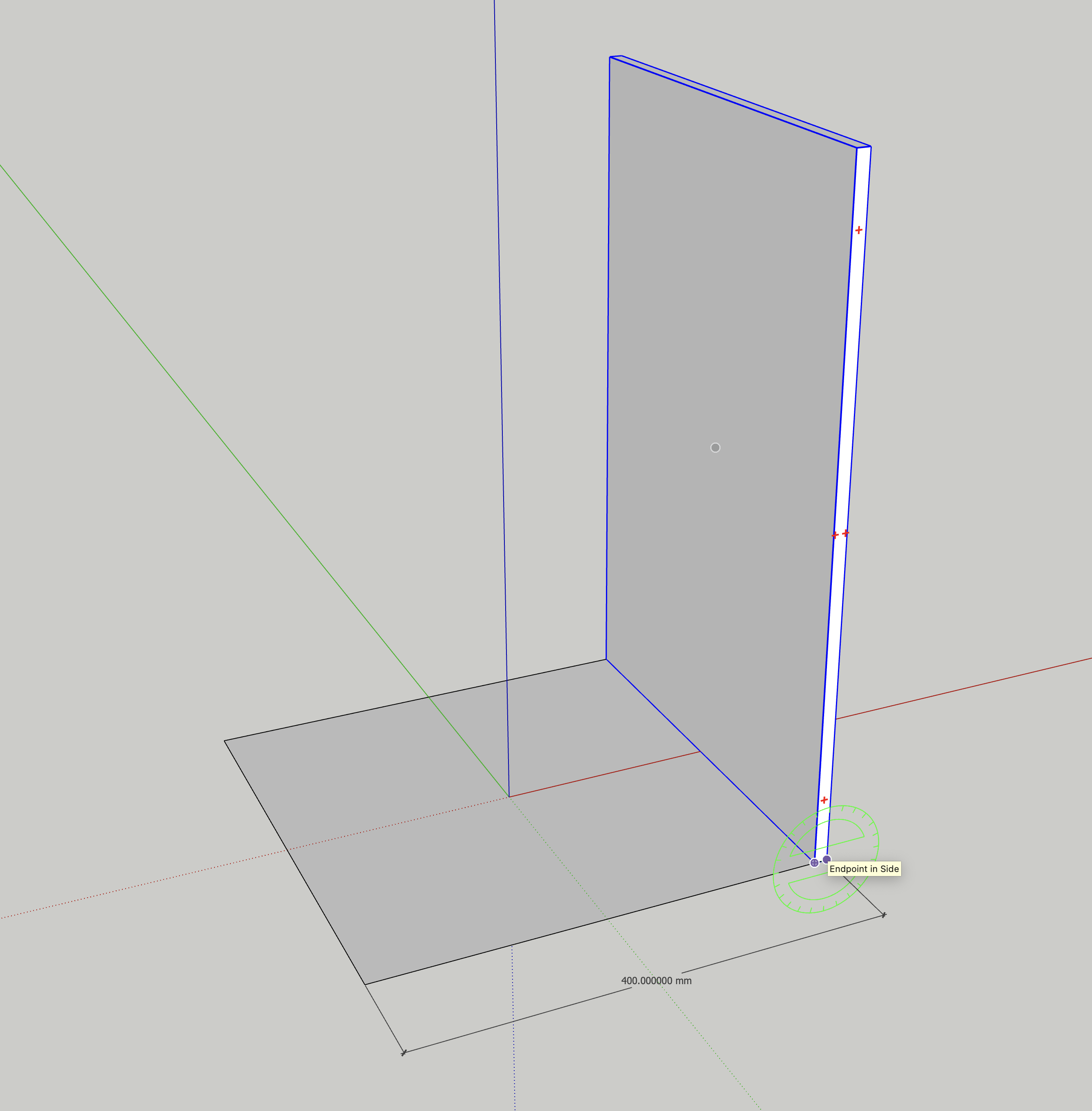
Rotate each panel individually to 7 degree leaning outward from eachother, now leaving 2 diagonal corners to be roughly 91 degree and the other 2 95-97 degree. Everything off square from eachother, now making an parallelogram, not a box.
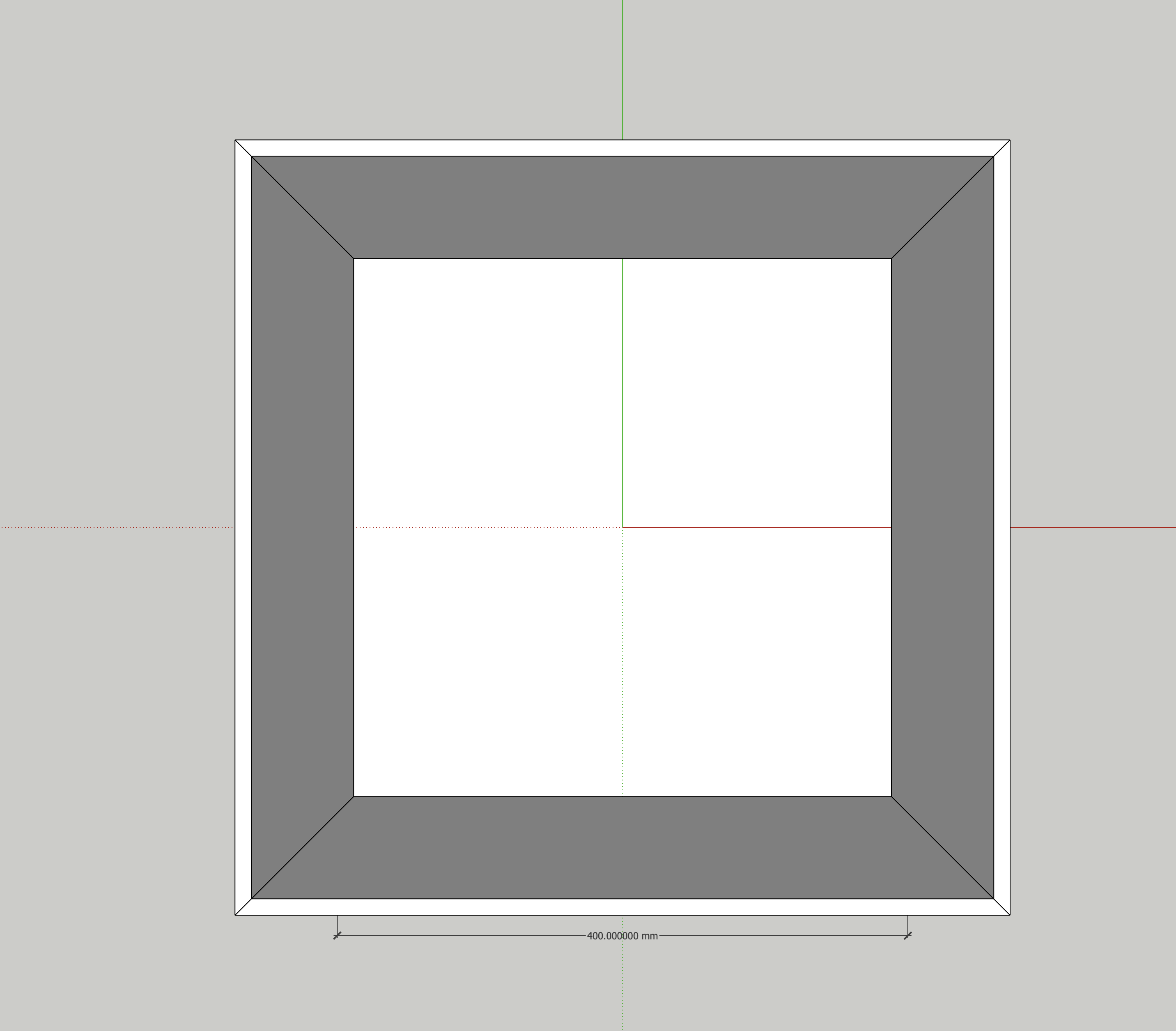
You might just post your model. In plan view the edges of the sides should be 90º to each other.
The cuts on the edges of the panels will not be 90º though.
Ive just returned everything back to a 90 degree straight, and none of the corners are aligned. I have 0 clue what the heck has happened. It was all perfect before. SO frustrating!
Hopefully this works for you. This is where its at now, after the leaning out by 7degree, then bringing it back in 7 degrees. Nothing is aligned now. It was before hand, all 90 degree cornered butt joints. Picket Planter.skp (172.6 KB)
I think you’d find it easier to manage if you work centered on the origin.
With the sides angled at 7° the edges of the legs on the narrower sides will need to be beveled slightly. They don’t meet the neighboring leg at 90°. It’s very slightly off the 90° but a couple of swipes with a hand plane during assembly will take care of it. Probably not worth modeling the bevels in SketchUp.
If the sides are all angles at 7 degrees outwards, yes.
I dont know why mine arent doing that.
Id like to get this working so I can print it off etc, but as ive mentioned previously, it keeps failing and ive done this like 4 times or something, and its driving me nuts
Im still relatively new to SketchUp, so im learning as I go. Trying to do small or simple projects. Perhaps this one was a teensy bit ambitious
What I see in your model shows mainly incorrect rotation of the components. You could make a frustum as a component and build your model around it using it as a reference. I did that for the first side when I modeled my version of it. After the legs for one side were done I deleted the frustum, added the rails and panel components and then used Copy/Flip to make the opposite side followed by Rotate/Copy to make the two remaing sides. Make Unique was required on the left and right sides to be able to edit the lengths of the rail components without affecting the front and back rails and panels.
As per your question, I dont know why mine in the beginning were all 90 degree to eachother, but then once I splayed them out 7 degrees were not longer square and shifted, like in the model now, and screenshot.
I dont know what a frustum is.
Im sorry, im going to have to look over your comment several times before I understand it, as I am new still, as ive mentioned, and im still learning tools/short cuts etc.
The way I made mine was by making the legs of 1 long panel, then the top, then the bottom, added in the 2 inner panels, selected all those parts and copy paste, rotate tool and spun it 180, then the same for the shorter sides. But clearly my method is screwing things up, and I could be more efficient and precise by the sounds of it.